Vacuum truck with collapsible scraper and pivot relief

a vacuum truck and scraper technology, applied in the direction of suction cleaners, way cleaning, construction, etc., can solve the problems of difficult scraping and cleaning, poor visibility of operators, and difficult use of equipment, so as to facilitate fast transport and reduce the risk of damage

Active Publication Date: 2011-02-22
MENSCH DONALD L
View PDF17 Cites 3 Cited by
  • Summary
  • Abstract
  • Description
  • Claims
  • Application Information

AI Technical Summary

Benefits of technology

[0003]In one aspect of the present invention, a scraper truck includes a powered steerable wheeled vehicle, a liftable main scraper mounted to the wheeled vehicle, and a vacuum system on the vehicle for suctioning material collected by the main scraper. The truck further includes right and left side scrapers mounted to opposite ends of the main scraper and pivotally movable between extended lateral positions where the side scrapers extend outboard of the opposite ends of the main scraper for collecting debris located outboard of a width of the vehicle, and a retracted position where the side scrapers are positioned in front of the main scraper in overlapped juxtaposed storage positions close to the main scraper to facilitate fast transport with minimal risk of damage.
[0004]In another aspect of the present invention, a scraper truck includes a powered steerable wheeled vehicle frame defining a longitudinal axis and including a scraper mount. A scraper assembly is attached to the wheeled vehicle by the scraper mount, the scraper assembly including a scraper with a front face that is concavely shaped and that extends generally perpendicular to the longitudinal axis. A vacuum system is mounted on the vehicle for suctioning material collected by the scraper. The truck further includes the scraper mount defining a centrally-located vertical pivot axis and the scraper assembly being rotatable about the vertical pivot axis such that upon striking an object toward an end of the scraper the risk of damage is minimized. A biasing mechanism is provided for biasing the scraper toward a centered forwardly-facing position.
[0005]In another aspect of the present invention, a scraper truck includes a powered steerable wheeled vehicle, a scraper assembly mounted to the wheeled vehicle, and a vacuum system on the vehicle for suctioning material collected by the scraper assembly. The scraper assembly includes a main scraper and also right and left side scrapers pivotally mounted by pivot structure to opposite ends of the main scraper. Actuators, connected with connecting structure, extend between each of the side scrapers and the wheeled vehicle to move the side scrapers between extended lateral positions where the side scrapers extend outboard of the opposite ends of the main scraper for collecting debris located outboard of a width of the vehicle, and a retracted position where the side scrapers are positioned in front of the main scraper for transport. Shear pins are placed in one or both of the pivot structures and the connecting structures to shear when an obstruction is impacted by the scraper assembly to avoid damage to components.

Problems solved by technology

A problem is that aisles along and between stalls are often narrow (or irregular in width or direction), poorly lighted, and include obstructions (e.g., numerous irregularities and protruding objects), making them very difficult to scrape and clean.
Presently known equipment is difficult to use and often provides poor visibility to the operator, poor control over scrapers, and further is cumbersome, overly complex, and difficult to repair.
Further, known equipment is not well-configured for fast transport, such that the equipment often gets damaged when traveling quickly between barn locations .
. . or cannot be driven quickly.

Method used


Image

  • Vacuum truck with collapsible scraper and pivot relief
  • Vacuum truck with collapsible scraper and pivot relief
  • Vacuum truck with collapsible scraper and pivot relief

Examples


Embodiment Construction

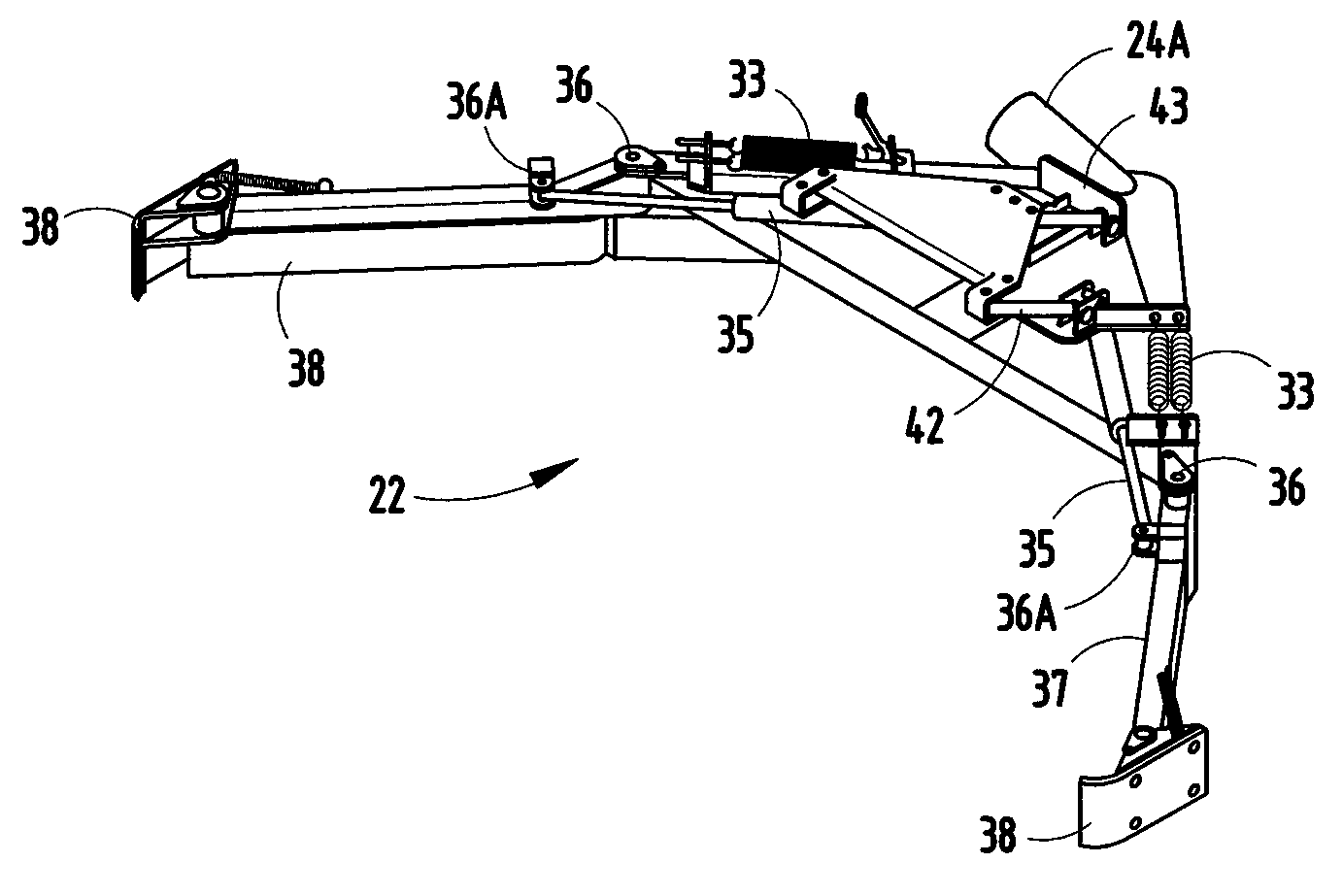
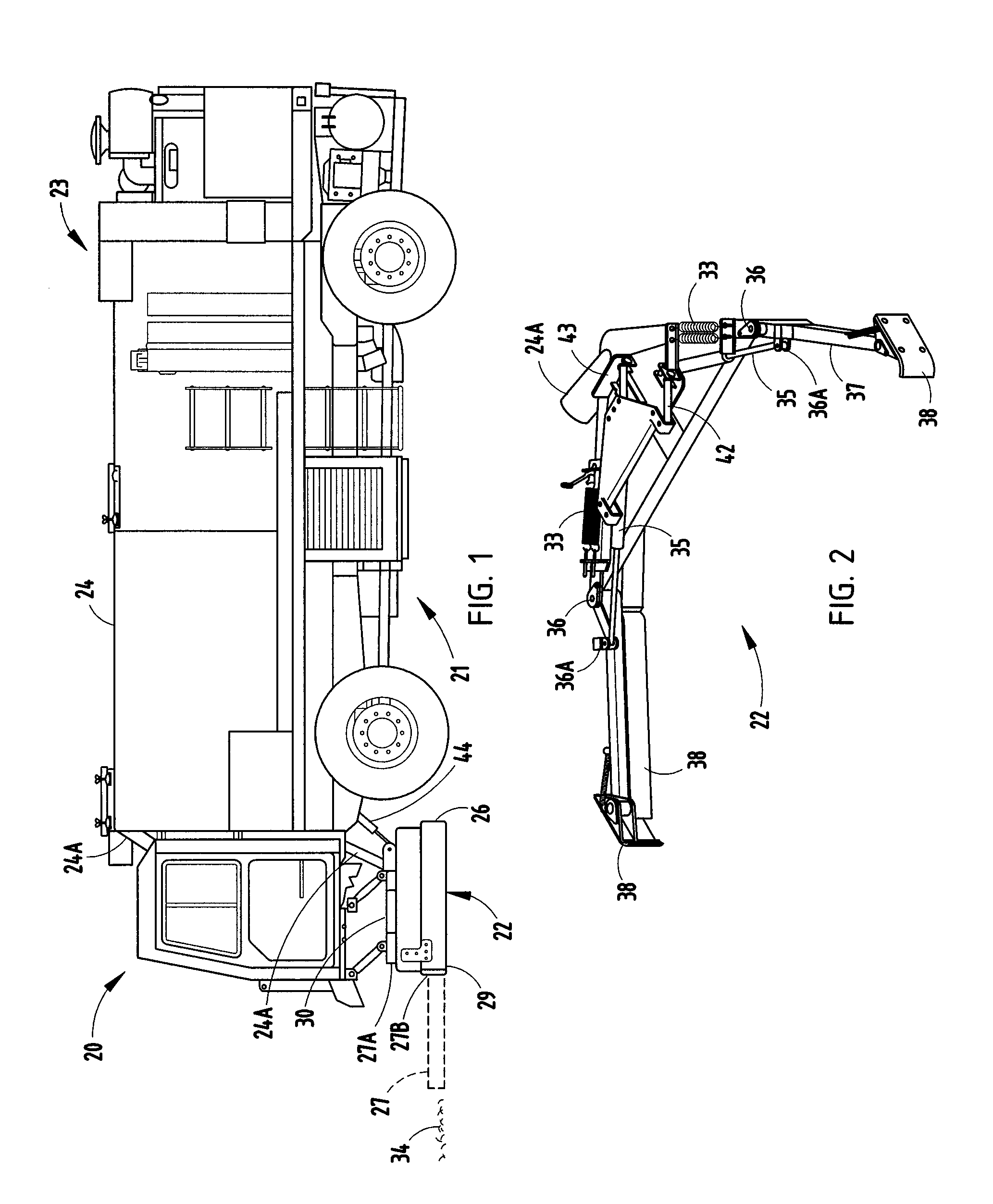
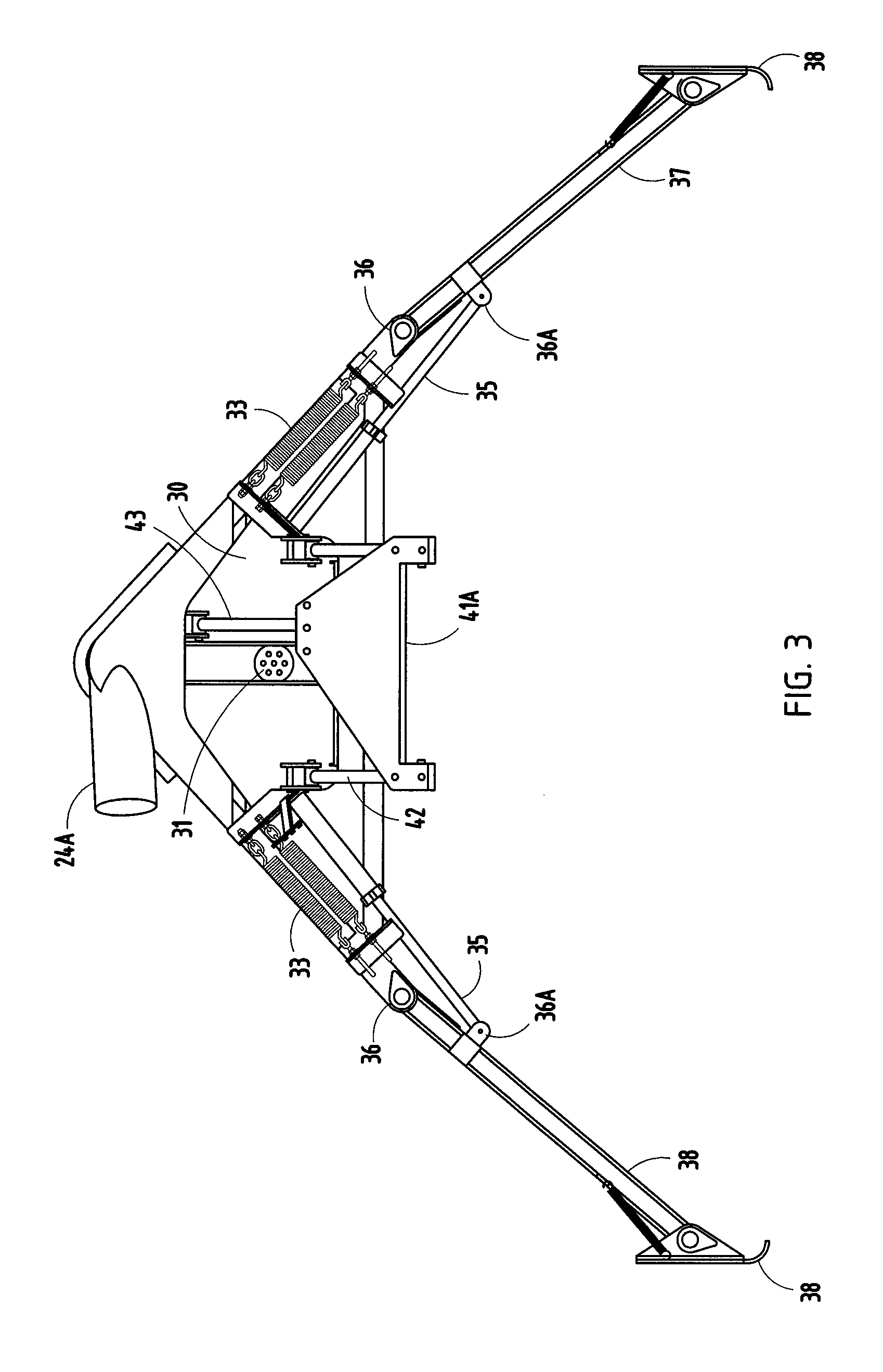
[0011]A scraper truck (or vehicle) 20 (FIG. 1) includes a powered steerable wheeled vehicle frame 21 with front-located windowed driver's cabin, a retractable liftable scraper assembly 22 mounted to the wheeled vehicle frame 21 under the cabin, and a vacuum system 23 with tank 24 on the truck 20 for suctioning collected debris material 34 collected by the scraper assembly 22 along a semi-rigid flexible suction line 24A. The scraper assembly 22 includes a main scraper 26 and left and right side scrapers 27 and 28 pivotally mounted to opposite ends 29 and 30 of the main scraper 26. The side scrapers 27 and 28 are horizontally pivotally movable by actuators 27A and 28A about vertical pivots 27B and 28B between extended lateral positions (FIGS. 2-5) where the side scrapers 27 and 28 extend outboard and forward of the opposite ends of the main scraper 26 for collecting debris 34 (e.g., animal manure and bedding material) located outboard of a width of the truck 20 (such as debris 34 loca...


PUM


Abstract

A scraper truck includes a main scraper mounted to a wheeled vehicle and side scrapers pivoted to the main scraper at its ends. The side scrapers are pivotally movable between extended lateral positions where the side scrapers extend outboard of the opposite ends for collecting debris located outboard of the vehicle's width, and a retracted position where the side scrapers are in overlapped juxtaposed storage positions close to and in front of the main scraper. The main scraper has a front face that is concavely shaped. The scraper mount defines a vertical pivot axis and the scraper assembly is rotatable about the vertical pivot axis upon striking an object toward an end of the scraper. A biasing mechanism is provided for biasing the scraper toward a centered forwardly-facing position, and a shear pin is configured to break prior to damage to the scraper or vehicle frame.

Description

BACKGROUND[0001]The present invention relates to scrapers for vacuum trucks, such as for collection of manure and stall material from animals in large farm operations.[0002]Large farming operations need to regularly remove manure and bedding. A problem is that aisles along and between stalls are often narrow (or irregular in width or direction), poorly lighted, and include obstructions (e.g., numerous irregularities and protruding objects), making them very difficult to scrape and clean. Further, equipment must often be moved significant distances between barns in order to take care of the various barns. Presently known equipment is difficult to use and often provides poor visibility to the operator, poor control over scrapers, and further is cumbersome, overly complex, and difficult to repair. Further, known equipment is not well-configured for fast transport, such that the equipment often gets damaged when traveling quickly between barn locations . . . or cannot be driven quickly....

Claims


Application Information

Patent Timeline
Patent Type & Authority Patents(United States)
IPC IPC(8): E01H1/08E01H5/04
CPCE01H1/106A01K1/0128
Inventor MENSCH, DONALD L.
Owner MENSCH DONALD L
Why Eureka
Try Eureka