Control device for a vehicle

a control device and vehicle technology, applied in the direction of propulsion parts, propulsion using engine-driven generators, process and machine control, etc., can solve the problem of time, achieve the effect of suppressing a heat generation amount, facilitating the reduction of the temperature of the electric motor, and enhancing the cooling effect of the electric motor

Inactive Publication Date: 2013-06-13
TOYOTA JIDOSHA KK
View PDF3 Cites 30 Cited by
  • Summary
  • Abstract
  • Description
  • Claims
  • Application Information

AI Technical Summary

Benefits of technology

[0022]According to the control device for a vehicle in the invention recited in the first aspect of the present invention, since if temperature of an electric motor exceeds predetermined temperature, the electric motor is rotated after a power transmission path between wheels and the electric motor is interrupted by a clutch device, lubricant oil supplied for cooling the electric motor is supplied in a larger amount or in a broader area, enhances the cooling effect of the electric motor as compared to the case that the electric motor is not rotated, thereby facilitating the reduction in temperature of the electric motor.
[0023]According to the control device for a vehicle in the invention recited in the second aspect of the present invention, since after the power transmission path between the wheels and the electric motor is interrupted by the clutch device, the electric motor is rotated by using an engine disposed as a drive force source of a vehicle, the rotation of the electric motor in an unloaded state suppresses a heat generation amount from the electric motor and, therefore, the reduction in temperature of the electric motor can further be facilitated.
[0024]According to the control device for a vehicle in the invention recited in the third aspect of the present invention, since after the power transmission path between the wheels and the electric motor is interrupted by the clutch device, the electric motor is rotated by using another electric motor, the rotation of the electric motor in an unloaded state suppresses a heat generation amount from the electric motor and, therefore, the reduction in temperature of the electric motor can further be facilitated.
[0025]According to the control device for a vehicle in the invention recited in the fourth aspect of the present invention, since after the power transmission path between the wheels and the electric motor is interrupted by the clutch device, the electric motor is rotated by supplying a drive current to the electric motor, the lubricant oil supplied for cooling the electric motor is supplied in a larger amount or in a broader area, enhances the cooling effect of the electric motor as compared to the case that the electric motor is not rotated, thereby facilitating the reduction in temperature of the electric motor.
[0026]According to the control device for a vehicle in the invention recited in the fifth aspect of the present invention, since a cooling device having a lubrication oil supply oil passage supplying lubrication oil from inner circumferential side of the electric motor to the electric motor, the cooling device cooling the electric motor with lubrication oil supplied from the lubrication oil supply oil passage and splashed outward by a centrifugal force generated by rotation of a rotor of the electric motor is comprised, an amount of the lubrication oil splashed outward from the rotor of the electric motor and supplied to a stator of the electric motor, for example is increased by rotating the electric motor, thereby enhancing the cooling performance of the electric motor.
[0027]According to the control device for a vehicle in the invention recited in the sixth aspect of the present invention, since a cooling device applying lubrication oil to the electric motor from outside of the electric motor for cooling the electric motor is comprised, the rotation of the electric motor changes a region to which the lubrication oil is applied in the electric motor, and the lubrication oil is applied to a broader area, thereby enhancing the cooling performance of the electric motor.

Problems solved by technology

The conventional control devices for a vehicle of Patent Documents 1 and 2 have a problem that time is required until the temperature of the electric motor is sufficiently reduced after the power transmission path between the electric motor and the wheels is interrupted since the electric motor includes an assembly of laminated steel plates and has a large heat capacity and a temperature of the electric motor hardly decreases once the temperature is raised.
The control device for a vehicle of the Patent Document 3 produces effect that a heat generation amount of the electric motor is reduced while the electric motor and the wheels are connected in a power transmittable manner, during output of the electric motor, and during running of a vehicle, and therefore has a problem that the effect is not produced when power transmission between the electric motor and the wheels is interrupted, when a vehicle is stopped, or when output is not executed by the electric motor, for example.

Method used


Image

  • Control device for a vehicle
  • Control device for a vehicle
  • Control device for a vehicle

Examples


first embodiment

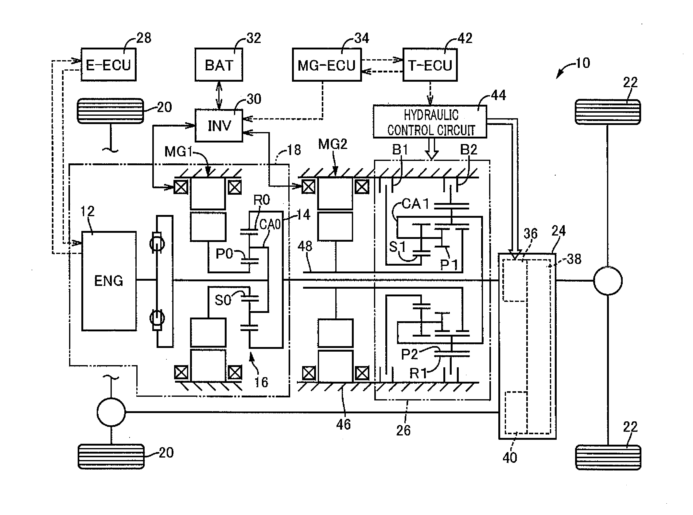
[0059]FIG. 1 is a schematic for explaining a configuration of a hybrid vehicle drive device 10 of one embodiment of the present invention. The hybrid vehicle drive device 10 has an engine 12 as a main drive force source of a vehicle and a differential mechanism 16 distributing power from the engine 12 to a first motor generator MG1 and a transmitting member 14, and includes an electric transmission portion 18 controlling a gear ratio in a stepless manner through control of an operation state of the first motor generator MG1; a power distribution device (transfer) 24 distributing power from the transmitting member 14 to each of front and rear wheels, i.e., front wheels 20 and rear wheels 22; a second motor generator MG2 disposed between the differential mechanism 16 and the power distribution device 24 in a manner enabling power transmission to the transmitting member 14; and an automatic transmission 26 outputting power of the second motor generator MG2 at different speeds. The hybr...

second embodiment

[0098]Other embodiments of the present invention will be described. In the description of the following embodiments, the mutually overlapping portions of the embodiments are denoted by the same reference numerals and will not be described.

[0099]FIG. 8 is a functional block diagram for explaining a main portion of control function included in an electronic control device 110 of another embodiment of the present invention. The electronic control device 110 controls the hybrid vehicle drive device 10 of FIG. 1. In FIG. 8, an electric motor cooling facilitating means 112 is different from the electric motor cooling facilitating means 102 of the first embodiment in the following point. When the off-road running mode is established or when the sub-transmission 36 is switched to the low-speed gear stage for off-road running, if the temperature TMG of the second motor generator MG2 exceeds the predetermined temperature temp1 set in advance, the electric motor cooling facilitating means 112 ...

third embodiment

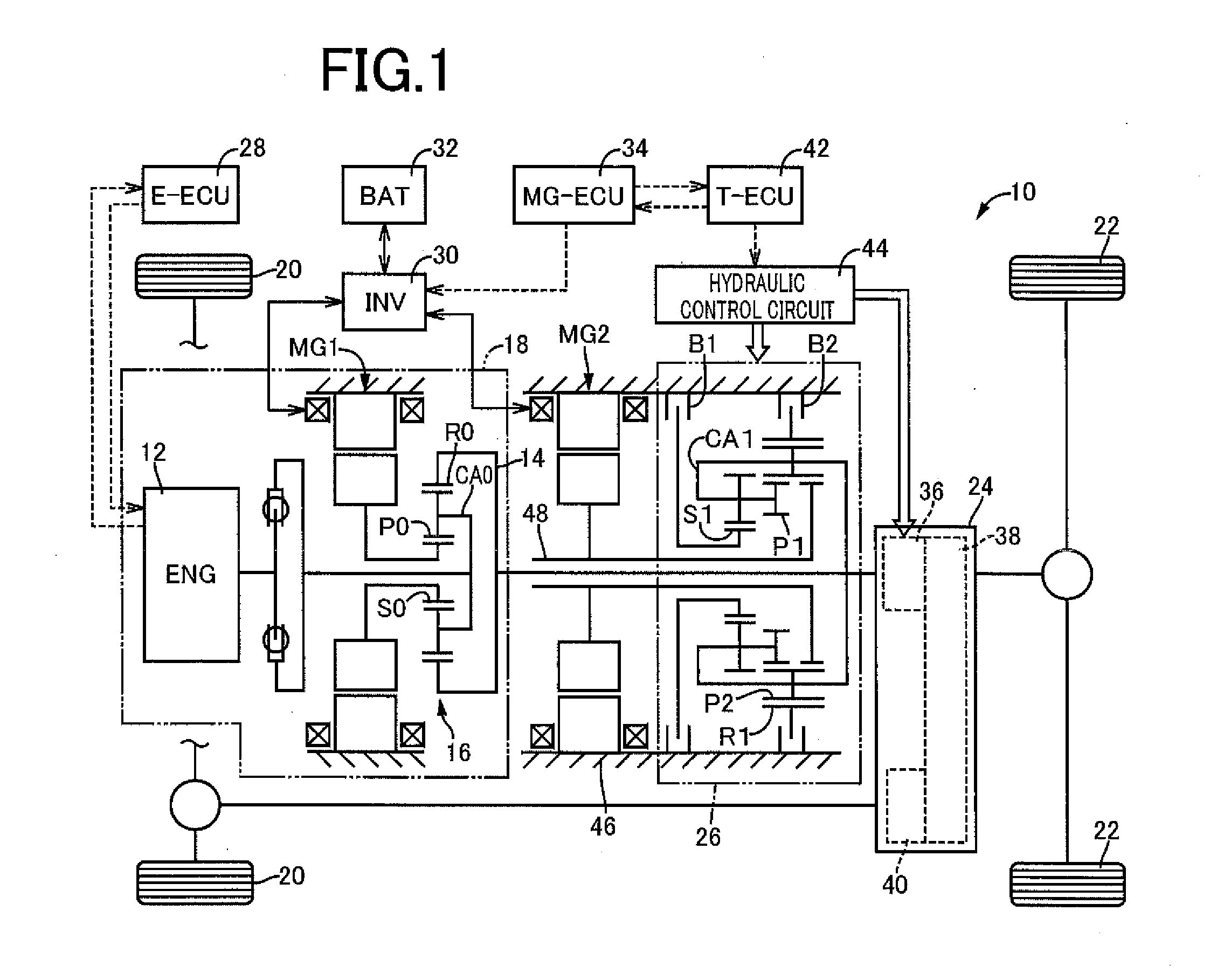
[0106]FIG. 10 is a diagram of a cooling device 122 included in a hybrid vehicle drive device 120 of another embodiment of the present invention. The hybrid vehicle drive device 120 is different from the hybrid vehicle drive device 10 of FIG. 1 in that the cooling device 122 is disposed instead of the cooling device 60. As depicted in FIG. 10, the cooling device 122 includes the electrically-powered oil pump 62, the lubrication pressure control solenoid valve 64 controlling an output oil pressure by using lubrication oil pumped from the oil pump 62 as an original pressure, and a lubrication oil supply tube 126 that consists of a tube-shaped member formed longitudinally in the axial center direction and fixedly disposed on the transmission case 46 on the outer circumferential side of the stator 52 of the second motor generator MG2 and that supplies the lubrication oil from the lubrication pressure control solenoid valve 64 to the second motor generator MG2 through lubrication oil disc...


PUM


Abstract

A control device for a vehicle includes an electric motor disposed in a manner enabling power transmission to wheels; and a clutch device capable of interrupting and connecting a power transmission path between the wheels and the electric motor, if temperature of the electric motor exceeds predetermined temperature defined in advance, the electric motor being rotated after the power transmission path between the wheels and the electric motor is interrupted by the clutch device.

Description

TECHNICAL FIELD[0001]The present invention relates to a control device for a vehicle including an electric motor and a clutch device disposed between the electric motor and wheels and particularly to a technique of facilitating reduction in temperature of the electric motor.BACKGROUND ART[0002]A control device for a vehicle is known that includes an electric motor in a manner enabling power transmission to wheels and a clutch device capable of interrupting and connecting a power transmission path between the wheels and the electric motor and that interrupts the power transmission path between the wheels and the electric motor with the clutch device if the temperature of the electric motor exceeds a predetermined temperature defined in advance. For example, this corresponds to those described in Patent Documents 1 and 2. Such a control device for a vehicle can suppress increase in temperature of the electric motor.[0003]Patent Document 3 describes a control device for a vehicle that ...

Claims


Application Information

Patent Timeline
Patent Type & Authority Applications(United States)
IPC IPC(8): H02K9/19B60W10/08B60W10/06B60W20/00B60W10/02B60L50/16
CPCB60K6/445Y02T10/7258B60K2001/003B60L2240/425B60W10/115B60W20/00B60W2510/087F16H57/0413F16H2037/0873H02P29/0044Y02T10/6239Y02T10/642B60W10/02B60W10/06B60W10/08H02K9/19Y10S903/93B60K6/365F16H2200/2023Y02T10/6286B60K6/547H02P29/60Y02T10/62Y02T10/64Y02T10/72B60W20/40B60W2710/021B60W20/50
Inventor MATSUBARA, TOORUTABATA, ATSUSHITAGA, YUTAKAUENO, YASUYUKIMINEKAWA, HIDETO
Owner TOYOTA JIDOSHA KK
Why Eureka
Try Eureka