Remote copy system and remote copy control method

Inactive Publication Date: 2013-06-13
HITACHI LTD
View PDF0 Cites 20 Cited by
  • Summary
  • Abstract
  • Description
  • Claims
  • Application Information

AI Technical Summary

Benefits of technology

[0009]Therefore, an object of the present invention is to enable the amount of data being sent and received between storage systems to b

Problems solved by technology

These communications charges account for a large percentage of the costs involved in operating a remote copy system.
However, the problem is that for a storage system, which does not comprise a data compression function, an appliance (a dedicated device) for compressing and sending data must be purchased and installed separately from the storage system, which is both costly and time consuming.
Another probl

Method used


Image

  • Remote copy system and remote copy control method
  • Remote copy system and remote copy control method
  • Remote copy system and remote copy control method

Examples


Example

Example 1

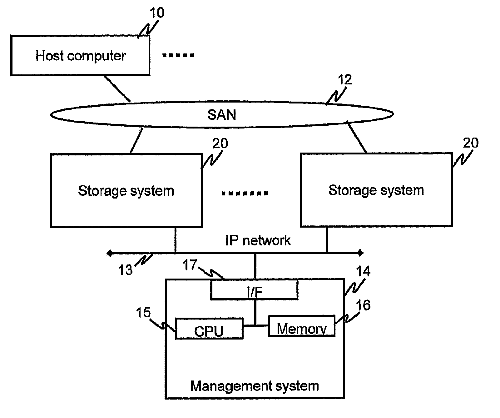
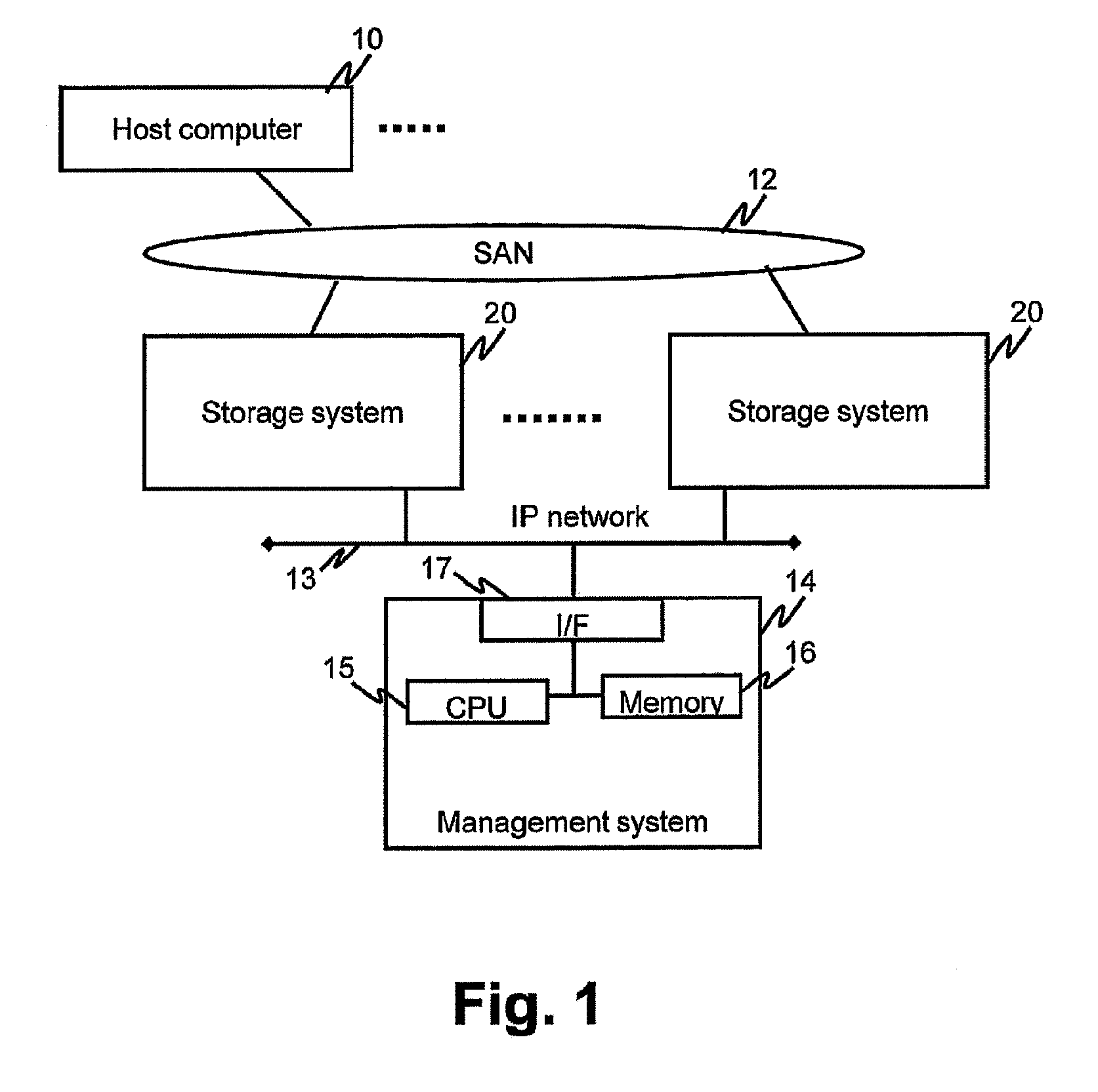
[0059]FIG. 1 shows an example of the configuration of a computer system related to Example 1.

[0060]The computer system comprises a host computer 10 and a remote copy system. The remote copy system comprises a management system 14 and multiple storage systems 20. The host computer 10 and the respective storage systems 20 are coupled by way of a first communication network, for example a SAN (Storage Area Network) 12. The respective storage systems 20 and the management system 14 are coupled by way of a second communication network, for example, an IP network (a communication network in which communications are performed in accordance with IP (Internet Protocol)) 13.

[0061]The management system 14 comprises a communication interface device 17, a storage device, and a control device coupled thereto. The communication interface device 17 is denoted as “I / F”. The storage device, for example, is a memory 16. The control device, for example, is a CPU (Central Processing Unit) 15. T...

Example

[0234]Example 2 will be explained hereinbelow. In so doing, the explanation will focus on the points of difference with Example 1, and explanations of the points in common with Example 1 will be either simplified or omitted.

[0235]FIG. 28 shows an overview of the processing of a remote copy system related to Example 2.

[0236]In Example 2, data transferred from the RAID group constituting the basis of the first VOL to the RAID group constituting the basis of the second VOL is routed through a third VOL. In this example, the RAID group constituting the basis of the first VOL of a first storage system 281 does not comprise a compression / decompression unit. Therefore, data is transferred from the first VOL to the second VOL as-is without being compressed.

[0237]Consequently, in this example, a third VOL, which is based on a RAID group comprising a compression / decompression unit, becomes the relay point of this data in order to reduce the amount of data, which is transferred to the second s...

Example

[0278]Example 3 will be explained below. In so doing, the explanation will focus on the points of difference with Example 1, and explanations of the points in common with Example 1 will be simplified or omitted. Furthermore, Example 3 can also be applied to Example 2.

[0279]FIG. 32 shows an overview of a remote copy system related to Example 3.

[0280]In Example 3, compressed data, which is to be transferred from a first VOL (transfer source) to a second VOL (transfer destination), is temporarily stored in a third VOL (storage destination), and thereafter, the compressed data is sent from the third VOL to the RAID group constituting the basis of the second VOL. Specifically, for example, the compressed data is transferred to the third VOL from the respective flash packages 29A, 29B, and 29C, which constitute the basis of the first VOL.

[0281]In Example 3, the compressed data may be stored in a storage device in the RAID group constituting the basis of the third VOL without actually goin...


PUM


Abstract

A first storage system comprises a first RAID group comprising multiple first storage devices, which constitute the basis of a first logical volume. A second storage system comprises a second RAID group comprising multiple second storage devices, which constitute the basis of a second logical volume. The RAID configuration of the first RAID group and the RAID configuration of the second RAID group are the same, and the type of a compression/decompression function of the respective first storage devices and the type of a compression/decompression function of the respective second storage devices are the same. Compressed data is read from a first storage device without being decompressed with respect to the data inside a first logical volume, and the read compressed data is written to a second storage device, which is in the same location in RAID in the second RAID group as the location in RAID of this first storage device.

Description

TECHNICAL FIELD[0001]The present invention relates to technology for remote copying performed between storage systems.BACKGROUND ART[0002]In a remote copy operation, a line (for example, a line of a WAN (Wide Area Network) managed by a telecommunications vendor may be leased, and remote copying may be performed between storage systems by way of this leased line. For this reason, when the amount of data being sent and received between the storage systems increases, communications charges rise proportionally. These communications charges account for a large percentage of the costs involved in operating a remote copy system. Therefore, the smaller the amount of data sent and received between storage systems the better.[0003]One method for reducing communications charges is to compress the data sent from the one storage system to the other storage system. However, the problem is that for a storage system, which does not comprise a data compression function, an appliance (a dedicated dev...

Claims


Application Information

Patent Timeline
IPC IPC(8): G06F12/08
CPCG06F3/0632G06F3/064G06F3/0685G06F3/0626G06F2212/401G06F3/0658G06F3/0689G06F11/1076G06F3/065
Inventor HARA, JUNICHIOGAWA, JUNJI
Owner HITACHI LTD
Why Eureka
Try Eureka