
Method, device and system for authenticating gateway, node and server

Active Publication Date: 2013-06-13
HUAWEI CLOUD COMPUTING TECH CO LTD
View PDF7 Cites 19 Cited by
  • Summary
  • Abstract
  • Description
  • Claims
  • Application Information

AI Technical Summary

Benefits of technology

The invention is about a system where a gateway receives information from a terminal node and verifies it. The node encrypts data with a unique key and sends it to the server, which also encrypts it using a shared key. The encrypted data is sent back to the node through the gateway. The node decrypts the data and checks if the server is valid. A new key is obtained and a secure channel is established with the gateway. This system ensures that even if the gateway is hacked, the security is not compromised. It improves security and reduces the risk of information breach.

Problems solved by technology

Due to the lack of unified M2M standards, M2M applications in vertical industries are commonly end-to-end solutions provided by individual manufactures, resulting in strong coupling of terminals and applications and higher deployment cost; furthermore, a large amount of deployed vertical industries form individual information isolated islands, for which information sharing is difficult, and duplication of construction is liable to occur.
All of these limit the further promotion of vertical M2M applications.
In M2M applications, personal devices can act as gateways, which have a risk of being hacked and controlled by hackers.
Whereas, in the prior art, gateways controlled by hackers can forge node login to disturb normal node operations, such as configuration parameter distribution failure, failing to acquire device data timely, unable to issue control commands in time, and etc, which may cause serious consequences.
Also, nodes do not authenticate gateways in the prior art, and therefore it is impossible for the node to apply corresponding security strategies according to a gateway identification, for example, whether to enable separate encryption of application data, or whether to enable integrity verification.

Method used


Image

  • Method, device and system for authenticating gateway, node and server
  • Method, device and system for authenticating gateway, node and server
  • Method, device and system for authenticating gateway, node and server

Examples


embodiment 1

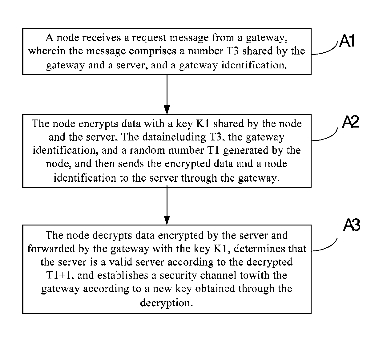
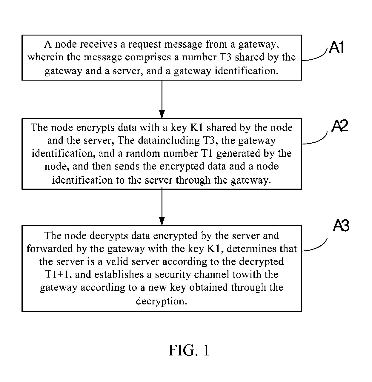
[0021]Referring to FIG. 1, a method for authenticating gateway, node and server according to embodiment 1 of this invention comprises the following steps:

[0022]A1. A node receives a request message from a gateway, wherein the message comprises a number T3 shared by the gateway and a server, and a gateway identification.

[0023]The gateway establishes a security session with the server and shares the number T3 with the server. The T3 is randomly generated by the server during the establishment of the security session, and is increased by one at each interaction between the gateway and the platform; the gateway sends the message to the node to request its node information, wherein the message carries the number T3 shared by the gateway and the platform, and an identification ID2 of the gateway.

[0024]A2. The node encrypts data with a key K1 shared by the node and the server, the data including T3, the gateway identification, and a random number T1 generated by the node; and sends the enc...

embodiment 2

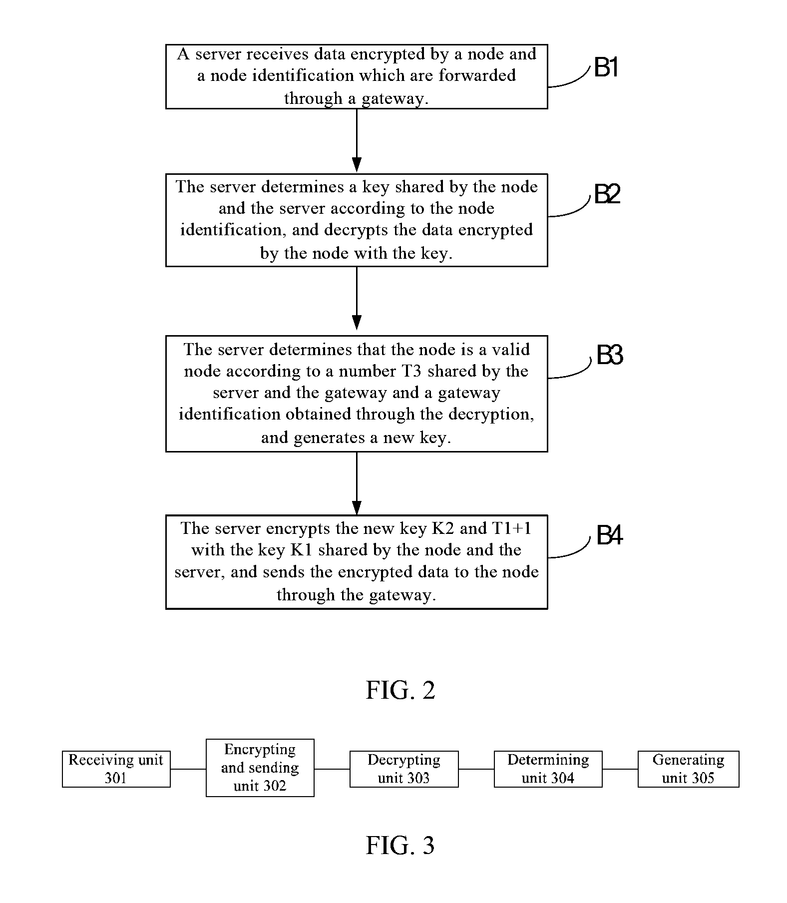
[0029]Referring to FIG. 2, a method for authenticating gateway, node and server is provided in embodiment 2 of this invention, comprising the following steps:

[0030]B1. A server receives data encrypted by a node and a node identification which are forwarded by a gateway.

[0031]The server receives the request for the node to join the network, sent by the gateway, and acquires the node identification ID1 and data encrypted by the node from the request.

[0032]B2. The server determines a key shared by the node and the server according to the node identification, and decrypts the data encrypted by the node with the key.

[0033]The server retrieves a key K1 shared by the server and the node according to ID1, and uses K1 to decrypt the data encrypted by the node.

[0034]B3. The server determines that the node is a valid node according to a number T3 shared by the server and the gateway, and a gateway identification obtained through the decryption; because T3 is originated from the server, and the...

embodiment 3

[0039]Referring to FIG. 3, a node is provided in an embodiment of this invention, comprising:

[0040]a receiving unit 301 for receiving information sent by a gateway, wherein the information comprises a number T3 shared by the gateway and a server, and a gateway identification; T3 is randomly generated by the server during establishment of a security session and is increased by one at each interaction between the platform and the gateway; the gateway sends a message, which carries the number T3 shared by the gateway and the platform and a gateway identification ID2, to the node to request its node information;

[0041]an encrypting and sending unit 302 for encrypting data with a key shared by the node and the server, the data including T3, the gateway identification, and a random number T1 generated by the node; and sending the encrypted data and a node identification to the server through the gateway; the node encrypts the following information with a key k1 shared by the node and the s...


PUM


Abstract

A method, device and system for authenticating gateway, node and server are provided in this invention. The node receives a message sent by a gateway, wherein the message comprises a number T3 shared by the gateway and a server, and a gateway identification. The node encrypts data with a key K1 shared by the node and the server, the data including T3, the gateway identification, and a random number T1 generated by the node, and then sends the encrypted data and a node identification to the server through the gateway. The node decrypts data encrypted by the server and forwarded by the gateway with the key, determines that the server is a valid server according to a T1-related number obtained by decryption, and establishes a security channel with the gateway according to a new key obtained through the decryption.

Description

CROSS-REFERENCE TO RELATED APPLICATIONS[0001]This application is a continuation of International Patent Application No. PCT / CN2011 / 073427, filed on Apr. 28, 2011, which claims priority to Chinese Patent Application No. 201010219330.1, filed on Jun. 30, 2010, both of which are hereby incorporated by reference in their entireties.FIELD OF THE INVENTION[0002]The present invention relates to the field of communication techniques, and more specifically, to a method, device and system for gateway, node and server authentication.BACKGROUND OF THE INVENTION[0003]M2M is the abbreviation of Machine-to-Machine communication, which, in a limited sense, refers to communications between machines through short range communication techniques, such as Zigbee. To put it simply, M2M brings machines all over the world into a communication network to make all machines intelligent, and no longer senseless. Generalized M2M further comprises human-to-machine and machine-to-human communications.[0004]M2M ap...

Claims


Application Information

Patent Timeline
IPC IPC(8): H04L9/32H04W4/70
CPCH04W4/005H04W12/04H04W12/10H04L9/321H04W84/18H04W12/06H04W4/70H04W12/041H04W12/106
Inventor BIAN, YONGGANGMU, LUNJIANWANG, JUEZHANG, YONGJINGHUANG, CHENGDING, CHUANSUO
Owner HUAWEI CLOUD COMPUTING TECH CO LTD
Learn More