
Adjustable Bent Drilling Tool Having in situ Drilling Direction Change Capability

Active Publication Date: 2013-06-20
DAVID L ABNEY
View PDF0 Cites 8 Cited by
  • Summary
  • Abstract
  • Description
  • Claims
  • Application Information

AI Technical Summary

Benefits of technology

The drilling tool assembly has the ability to change the direction of drilling in real-time, without having to bring the entire drill string up to the surface for manual reconfiguration. The mid-assembly module uses hydraulics to transmit and carry out electronic commands, which causes the drill tool to bend by a preset degree. The position of the drill tool is tracked using magnetic sensors and a stationary magnet. The safety release sub-assembly allows for the drill tool to be unbended and removed to the surface for maintenance or repairs through a hydraulic pressure shear release mechanism.

Problems solved by technology

Such a process is necessarily slow and laborious, and necessitates bringing the drill string to the surface for manual adjustment at regular intervals.
Not only is such a procedure time consuming and prone to substantial delays, but also increases unnecessary wear on drilling equipment during the reconfiguration process, thereby substantially increasing the cost for the production of in-situ fluids.

Method used


Image

  • Adjustable Bent Drilling Tool Having in situ Drilling Direction Change Capability
  • Adjustable Bent Drilling Tool Having in situ Drilling Direction Change Capability
  • Adjustable Bent Drilling Tool Having in situ Drilling Direction Change Capability

Examples


Embodiment Construction

[0025]The following detailed description provides a description of exemplary embodiments of the technology to facilitate an understanding of the technology, but does not limit the scope of the technology.

[0026]The term “exemplary” as applied to embodiments means “an example of.”

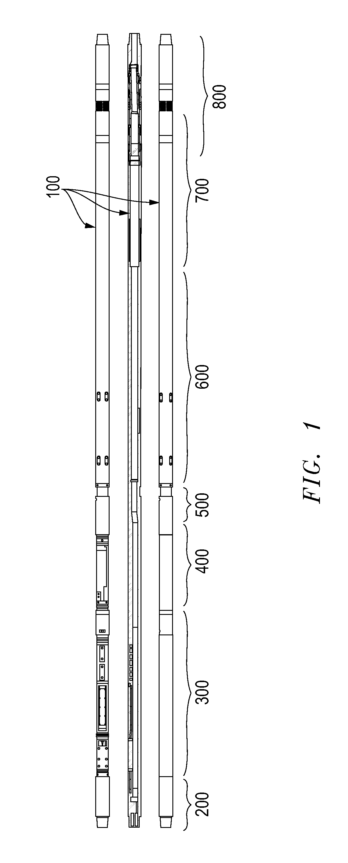
[0027]FIG. 1 illustrates an exemplary embodiment of a drilling tool 100 that is bendable in situ in a controlled manner on instructions from controls at the surface. Drilling tool 100 may also send feedback data to the surface and may be otherwise monitored from the surface. For ease of explanation, the tool may be regarded as having several modules, although some of these modules may be combined or separated into more component modules as a matter of design choice. In the exemplary embodiment of the present invention shown in FIG. 1, drilling tool 100 is shown with exemplary side views as well as a cross-sectional view of the entire tool. FIG. 1 further details an exemplary sequence for connecting various mo...


PUM


Abstract

An adjustable bent drilling tool capable of changing in situ drilling direction to facilitate horizontal drilling. The drilling tool may be controlled from the surface and eliminates the need to bring the tool to the surface for reconfiguration. In one embodiment, the drilling tool utilizes a communications module to communicate with upstream sections of the tool. The communications module is connected to a programmable electronic control module which controls an electric motor. A hydraulic valve assembly follows the control module, which receives input signals and controls a pilot piston between two fixed points of a mid-assembly typically located adjacent to and downstream of the hydraulic valve assembly on the drill tool. A lower assembly is attached to the drill tool immediately following the mid-assembly, and provides both a safety release sub-assembly as well as a bendable sub-assembly which directs the adjustable drill tool to change drilling angle and direction.

Description

BACKGROUND[0001]1. Field of the Invention[0002]The technology relates to drill tools used for drilling into geological structures, including but not limited to potential hydrocarbon-bearing structures, and more particularly to drill tools that include an assembly that has capability for a controlled change in the direction of drilling in situ.[0003]2. Description of the Related Art[0004]In the field of drilling technology, it has become well known to drill a bore vertically to a predetermined or selected depth. In one aspect of drilling technology, it is known to drill the borehole at a deviated angle from vertical. This form of drilling is known as “directional” drilling, which creates boreholes that approach a horizontal deviation. This is done by drilling down in the traditional sense, and then gradually curving the direction of drilling until a substantially horizontal drilling plane is achieved to enter a region that has or is believed to have a reservoir of a desired product, ...

Claims


Application Information

Patent Timeline
IPC IPC(8): E21B7/04E21B17/02
CPCE21B7/067E21B17/02E21B7/04
Inventor ABNEY, DAVIDCROW, MORGANMUSE, ANTHONY C.ORBAN, ANDREWEISE, STAN
Owner DAVID L ABNEY
Learn More