Battery state of charge sensor

Active Publication Date: 2013-06-20
METHODE ELETRONICS INC
View PDF5 Cites 34 Cited by
  • Summary
  • Abstract
  • Description
  • Claims
  • Application Information

AI Technical Summary

Benefits of technology

[0024]It is another object of the present invention to provide a sensor that can be easily mounted to the battery cell without adding substantial weight or requiring substantial change to the size of the battery cell, and that can be manufactured and

Problems solved by technology

However, because the charge is stored chemically, each charge-discharge cycle (as well as normal temperature cycling, vibration, shock etc.) results in irreversible changes within the individual cells.
Thus, the aforementioned method of subtracting the amount of charge used from the amount initially placed in the cell to determine the charge state is flawed because the actual charge capacity of the cell is reduced over time and actual usage at an unknown rate.
The risk of uncertainty of the actual state of battery charge is almost always that an inconvenience will result if the battery charge falls below useful levels.
In purely electric ve

Method used


Image

  • Battery state of charge sensor
  • Battery state of charge sensor
  • Battery state of charge sensor

Examples


Embodiment Construction

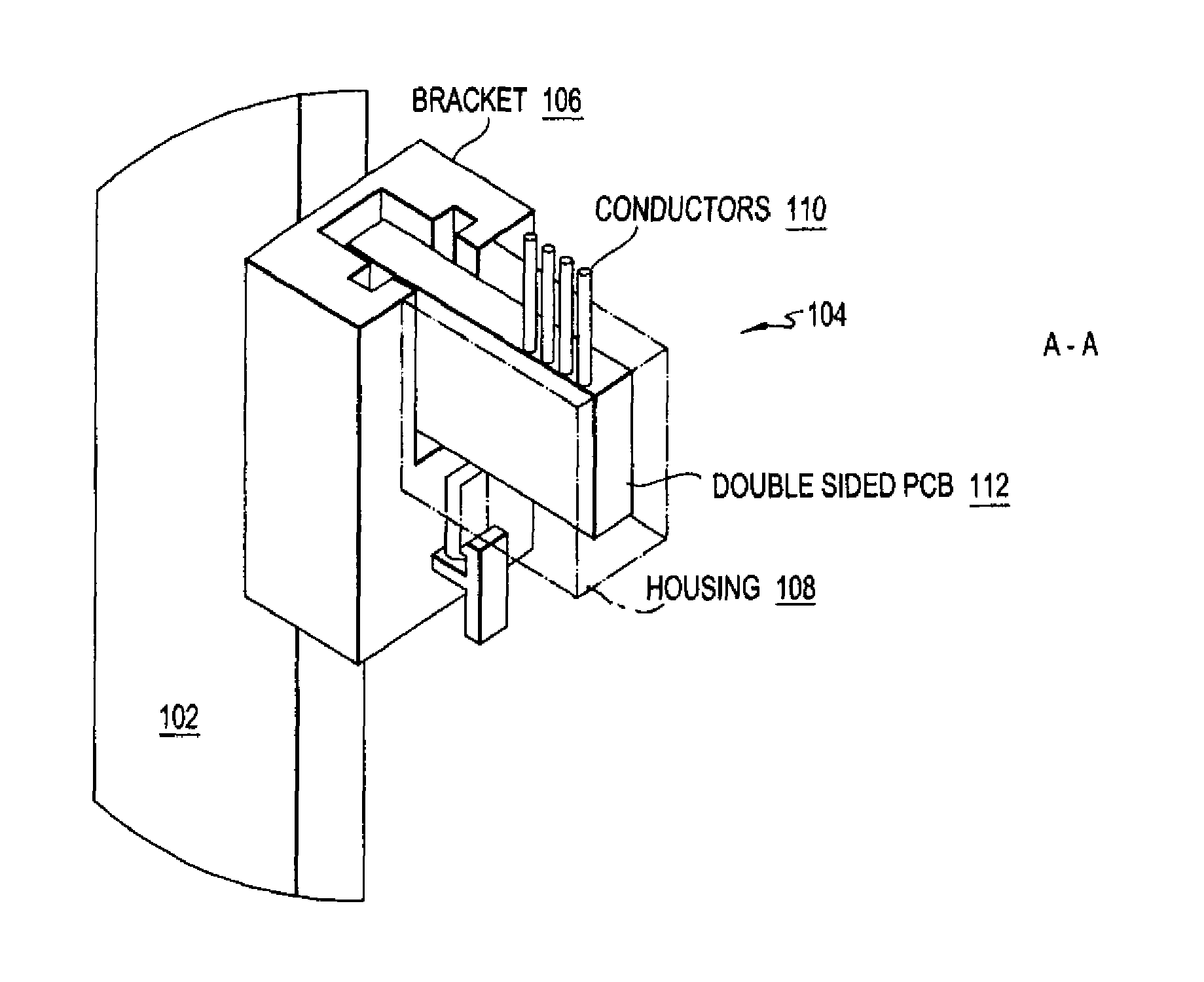
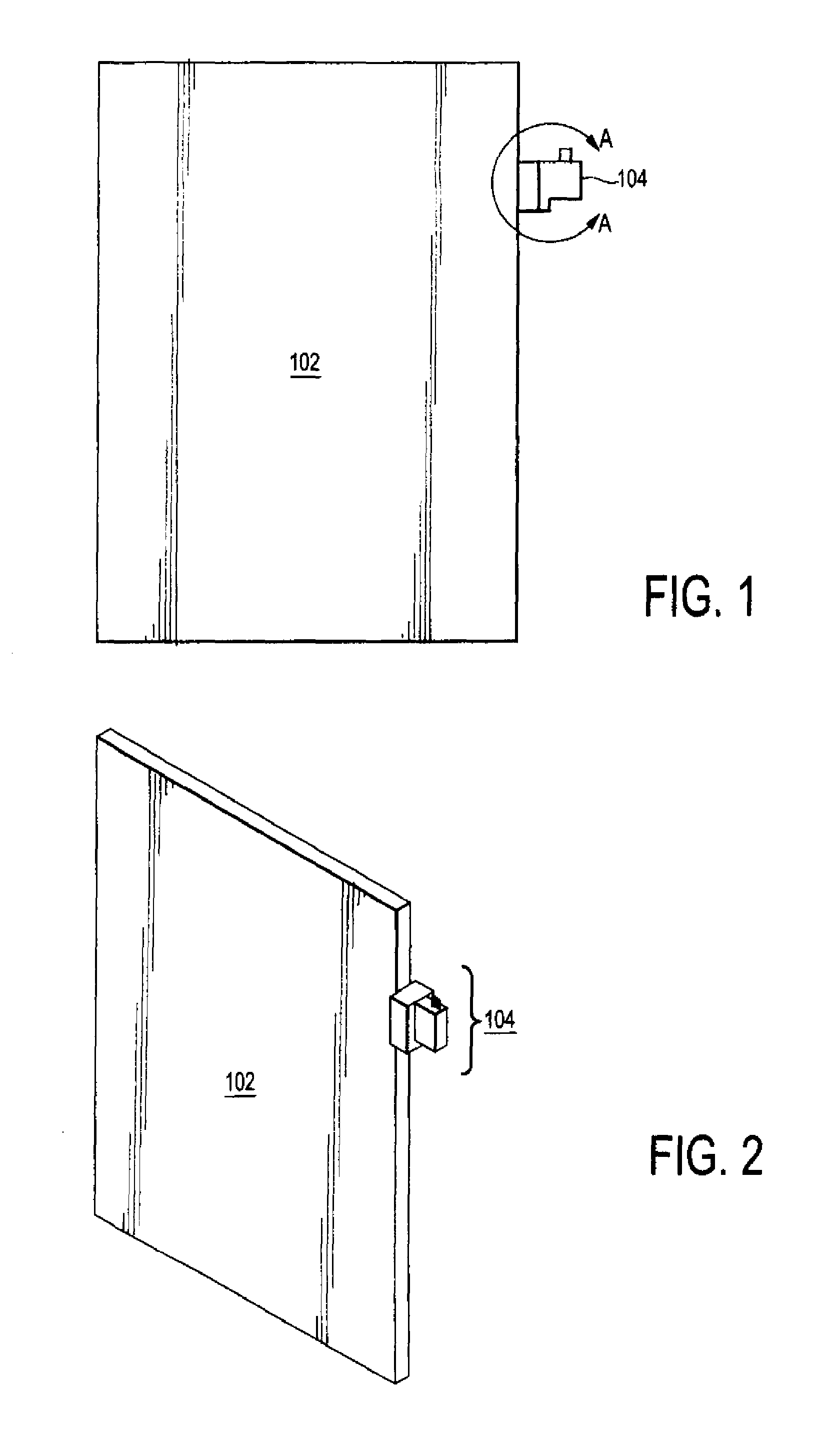
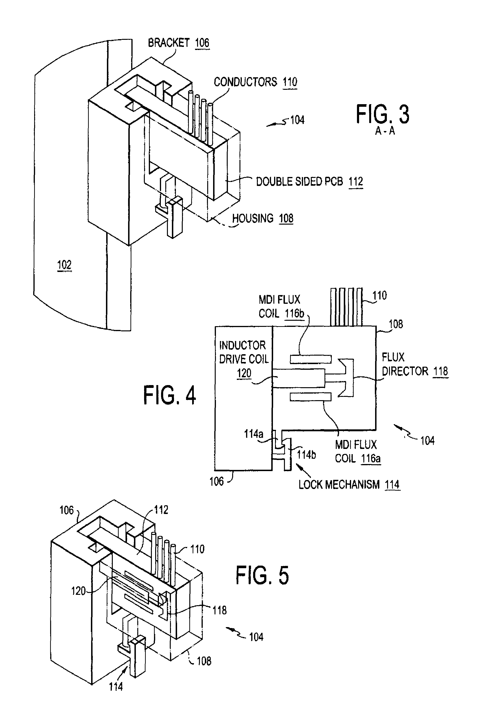
[0041]Several preferred embodiments of the invention are described for illustrative purposes, it being understood that the invention may be embodied in other forms not specifically shown in the drawing. The figures will be described with respect to the system architecture and methods for using the system to achieve one or more of the objects of the invention and / or receive the benefits derived from the advantages of the invention as set forth above.

[0042]The present invention is directed to a sensor for measuring the magnetic susceptibility of an object by generating a magnetic field that permeates the object and by sensing the resultant changes in that same magnetic field. The “object” may be a volume with constant or variable magnetic susceptibility, as may be related to some other physical quantity or condition. Examples of the physical condition include but are not limited to the material temperature, the concentration of ions in the material, or the structure of the material.

[0...


PUM


Abstract

The invention relates to an object's state or properties being monitored, such as a lithium-iron-phosphate (LFP) or other type of electrical battery containing one or more LFP or other type of electrical battery cell within the battery, and one or more sensors for measuring the state or property of the object, such as the state of charge of the battery cells, by measuring the magnetic susceptibility or other properties, such as the magnetic susceptibility of electrolyte or the electrodes within the battery cells. The state of charge of the battery cells within the battery arc monitored by the one or more sensors, which are coupled to electrical circuits.

Description

CROSS-REFERENCE TO RELATED APPLICATIONS[0001]This application is related to and claims priority to U.S. Provisional Application 61 / 150,091, filed Feb. 5, 2009, the content of which is incorporated herein by reference.BACKGROUND OF THE INVENTION[0002]1. Field of the Invention[0003]The present invention is directed to devices and methods for determining, monitoring, and providing an indication of the state of charge of an object, such as a battery, using detectable magnetic flux, the object being useful in a variety of application, including a battery useful in automotive passenger vehicles.[0004]2. Description of the Related Art[0005]A battery consists of one or more cells connected in a series and / or parallel arrangement that chemically store electrical charge potential (energy) and deliver the charge at a pre-determined voltage when demanded by an external electric circuit load. Each of the battery cells contain two half-cells connected in series by an electrolyte. An electrolyte c...

Claims


Application Information

Patent Timeline
IPC IPC(8): G01R31/36
CPCG01R31/3606H01M4/5825H01M10/052H01M10/486Y02T10/7011H01M10/425H01M10/48G01R31/382Y02E60/10H01M6/5044H01M10/44H01M50/572Y02T10/70
Inventor RICE, MARIA F.JONES, CHRISTOPHER
Owner METHODE ELETRONICS INC
Why Eureka
Try Eureka