Waveguide band-pass filter with pseudo-elliptic response

a band-pass filter and waveguide technology, applied in the field of waveguides, can solve the problems of not offering any solutions in the prior art, and achieve the effects of compact overall dimensions, good selectivity performance, and convenient manufacturing

Inactive Publication Date: 2013-06-20
POLITECNICO DI MILANO
View PDF8 Cites 10 Cited by
  • Summary
  • Abstract
  • Description
  • Claims
  • Application Information

AI Technical Summary

Benefits of technology

[0007]The problem on which the present invention is based is to provide an alternative waveguide band-pass filter in respect to those known and which, for example, allows an easy manufacturing, while offering good performances in terms of selectivity and keeping compact overall dimensions.

Problems solved by technology

The applicant has noted that, with reference to the waveguide band-pass filters, the prior art does not offer any solutions which enable to achieve an increase in filter selectivity by not complex manufacturing procedures.

Method used


Image

  • Waveguide band-pass filter with pseudo-elliptic response
  • Waveguide band-pass filter with pseudo-elliptic response
  • Waveguide band-pass filter with pseudo-elliptic response

Examples


first embodiment

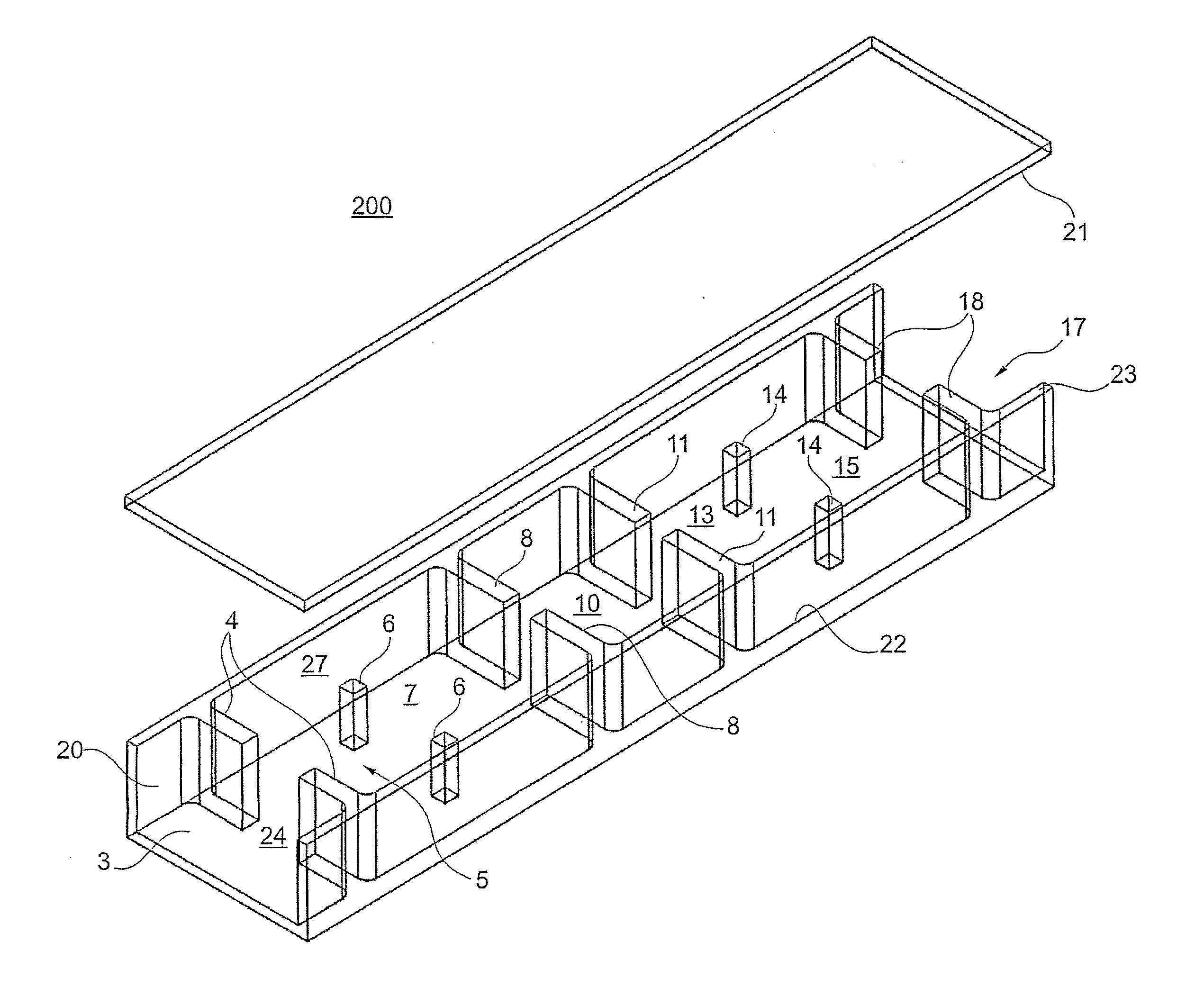
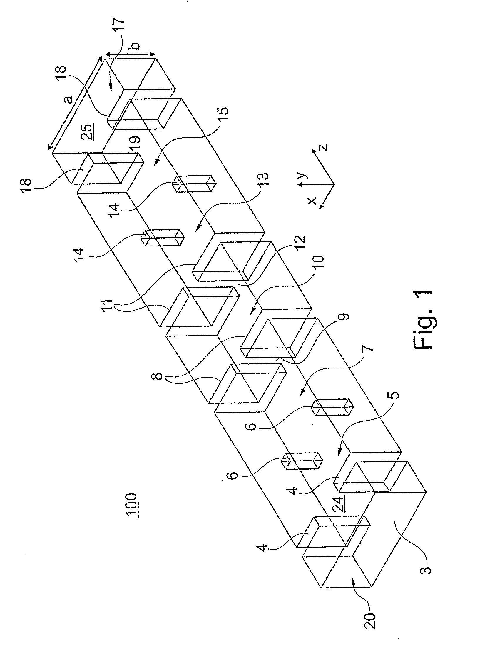
[0032]The first inductive discontinuity coupling device 4 can be made, by means of an iris or inductive diaphragm comprising two metal septums (also referred to by reference numerals 4) arranged symmetrically in respect to a median longitudinal plane, which develops parallel to an axis z of the radiation propagation. The metal septums 4 of the first inductive diaphragm identify a first coupling radiation opening 24 of the electromagnetic field.

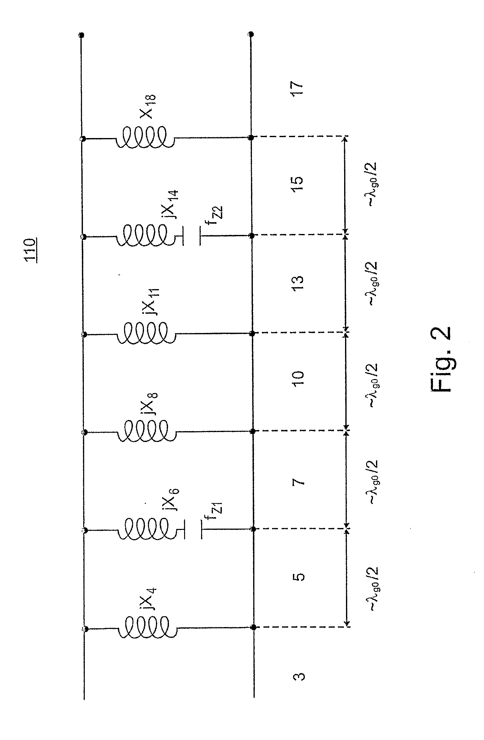
[0033]With reference to the equivalent electric scheme of FIG. 2, the first inductive diaphragm 4 is represented as an optimal shunt inductor having an inductive impedance jX4. The walls of the first inductive diaphragm 4 have the same height as the height b of filter 100.

[0034]The first resonator segment of the waveguide 5 has a length, taken on the axis z, approximately equal to half of length of the central wave of the filter: λg0 / 2 and it is coupled to the input 3 by the inductive diaphragm 4. The resonator segment 5 can also have a lengt...

embodiment 400

[0089]FIG. 14 refers to an embodiment 400 of the band-pass filter 100, which may be implemented by processing the low-loss dielectric slug, and suitable for the guided propagation of electromagnetic waves, obtaining hollow geometrical shapes which reproduce as a negative both the shape of the inductive coupling devices such as the diaphragms 4, 8, 11 and 18 and the resonant coupling devices (such as the two posts 6).

[0090]These cavities obtained in the dielectric slug are then coated with a metal material by a metallization step, which enables to obtain the four external walls of the waveguide of the dielectric filter 400. In particular, the dielectric-type filter 400 of FIG. 14 is a four-resonator band-pass filter with a transmission zero. For the sake of clarity of the depiction in FIG. 14, they are not shown.

[0091]FIG. 15 shows the behaviours of the reflectance S11 and transmittance S21 obtained by a numerical simulation with reference to an example of the dielectric filter 400 o...


PUM


Abstract

A waveguide band-pass filter is disclosed comprising: an input/output gate for a signal; a first inductive discontinuity coupling device; a second inductive discontinuity coupling device and a first waveguide resonator segment coupled to said input/output gate and interposed between the first and the second coupling devices. At least one of the first and the second coupling devices includes at least a resonant coupling structure which extends in the waveguide with a reduced height relative to a height of the first resonator segment and it is shaped for inputting a zero in a transmission frequency response of the filter.

Description

FIELD OF THE INVENTION[0001]The present invention refers to the field of waveguides and in particular to waveguide band-pass filters.PRIOR ART[0002]Waveguide band-pass filters are known which comprise a cascade of waveguide segments whose length is about half of the central wavelength of the filter (λ / 2) or multiples of such a value which act as resonators and are coupled to each other (and to input / output guides) by discontinuities such as, typically, diaphragm-structures. These coupling-discontinuities present an equivalent circuit having a shunt reactance. The reactance value, usually inductive, determines the entity of the coupling between the resonating guide segments.[0003]The synthesis of such waveguide filters, called “filters with directly-coupled resonator” is analysed in G. L. Matthaei, L. Young e E. M. T. Jones, “Microwave filters, Impedance-Matching Networks, and Coupling Structures” ed. McGraw Hill, 1964.[0004]U.S. Pat. No. 7,391,287 discloses a “H-plane” waveguide fil...

Claims


Application Information

Patent Timeline
Patent Type & Authority Applications(United States)
IPC IPC(8): H01P1/208
CPCH01P1/208H01P1/207H01P1/2016
Inventor POLITI, MARCO
Owner POLITECNICO DI MILANO
Why Eureka
Try Eureka