Display panel

a display panel and transparent technology, applied in the field of display panels, can solve the problems of damage to the organic light emitting material, the lack of transmittance properties the inability of the tft to improve the transmittance of the display panel, so as to reduce the likelihood of damage to other film layers

Inactive Publication Date: 2013-06-20
AU OPTRONICS CORP
View PDF7 Cites 29 Cited by
  • Summary
  • Abstract
  • Description
  • Claims
  • Application Information

AI Technical Summary

Benefits of technology

[0008]The invention provides a display panel which can resolve an issue of insufficient transmittance of a conventional transparent display panel or reduce the likelihood of causing damages to other film layers.

Problems solved by technology

The existing organic light emitting display panels are mostly capable of displaying images but are not equipped with transmittance properties.
Since the TFT occupies a small area, the TFT is not very helpful to improve the transmittance of the display panel.
Said design indeed increases transparency of the display panel, whereas the indium tin oxide formed on an organic light emitting material is apt to cause damages to the organic light emitting material.

Method used


Image

  • Display panel
  • Display panel
  • Display panel

Examples


Embodiment Construction

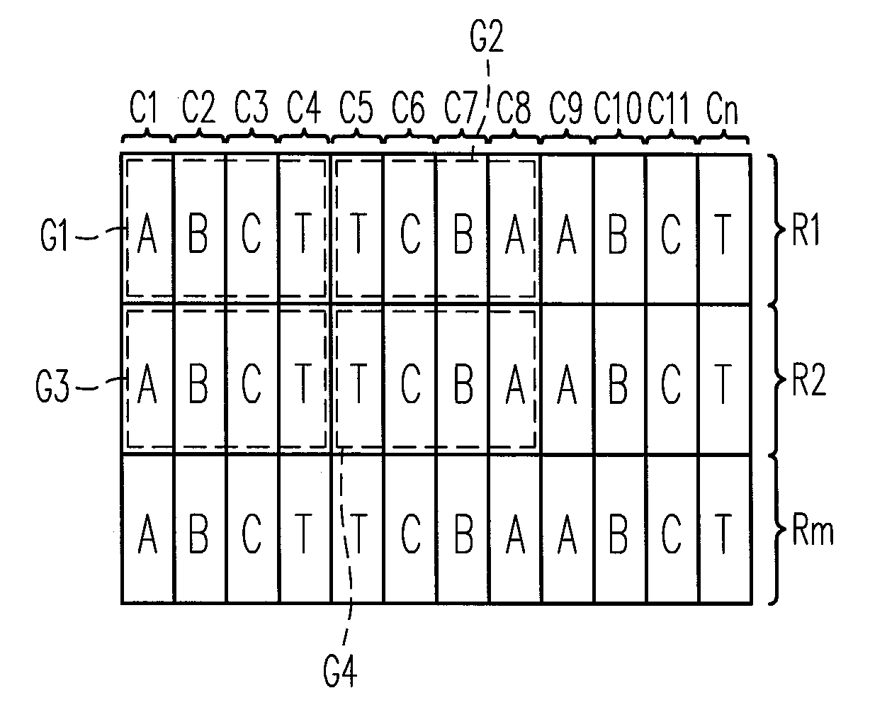
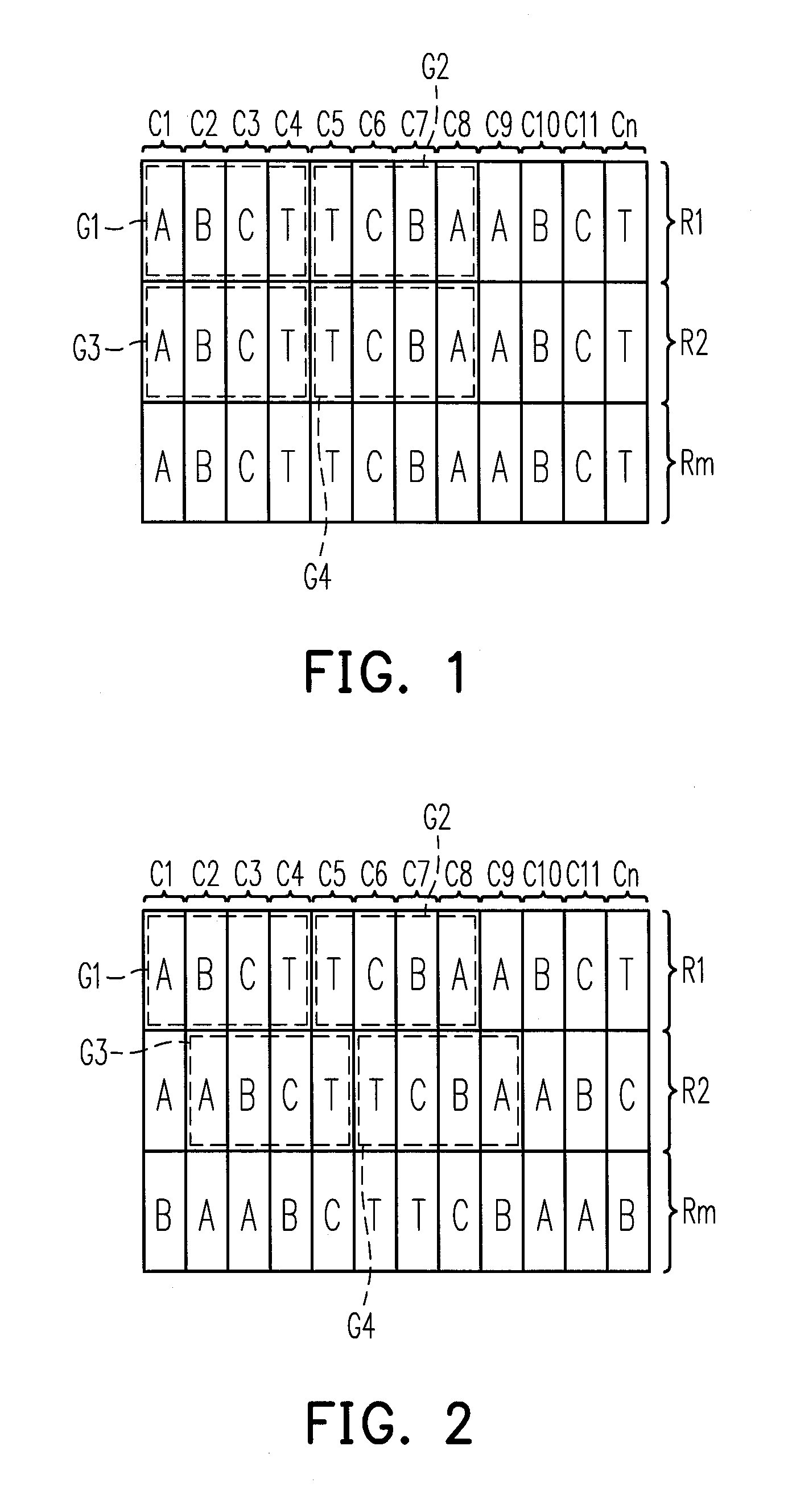
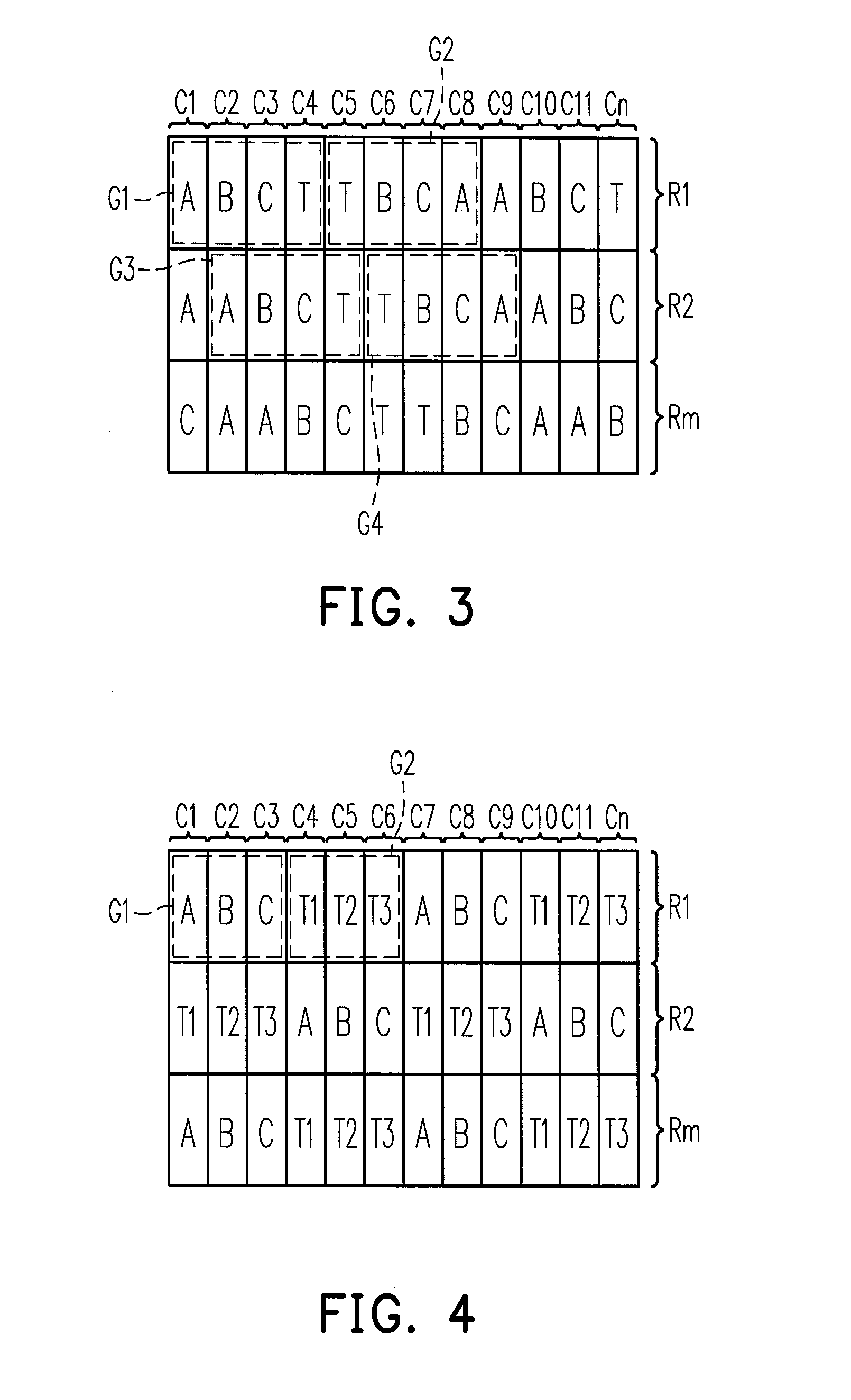
[0017]FIG. 1 is a schematic view illustrating a display panel according to an embodiment of the invention. With reference to FIG. 1, the display panel of this embodiment includes a pixel array arranged with a plurality of columns C1˜Cn and a plurality of rows R1˜Rm. As shown in FIG. 1, the columns C1˜Cn are arranged in an X direction, while the rows R1˜Rm are arranged in a Y direction. Hence, the columns C1˜Cn may be referred to as vertical columns, while the rows R1˜Rm may be referred to as horizontal rows. However, the invention is not limited thereto. According to another embodiment of the invention, the columns C1˜Cn are arranged in the Y direction, while the rows R1˜Rm are arranged in the X direction. That is to say, the columns C1˜Cn and the rows R1˜Rm described herein mainly serve to explain relative positions of arrays but do not serve to limit the invention. Hence, the positions of the columns C1˜Cn and the rows R1˜Rm may be exchanged. Besides, when the positions of the col...


PUM


Abstract

A display panel has a pixel array arranged with a plurality of columns and a plurality of rows. The display panel includes a first pixel group and a second pixel group arranged in the first row and adjacent to each other. The first pixel group and the second pixel group respectively include a first color sub-pixel, a second color sub-pixel, a third color sub-pixel, and a transparent sub-pixel. The arrangement of the first color sub-pixel, the second color sub-pixel, the third color sub-pixel, and the transparent sub-pixel of the first pixel group and the arrangement of the first color sub-pixel, the second color sub-pixel, the third color sub-pixel, and the transparent sub-pixel of the second pixel group are symmetric in mirror.

Description

CROSS-REFERENCE TO RELATED APPLICATION[0001]This application claims the priority benefit of Taiwan application serial no. 100146876, filed on Dec. 16, 2011. The entirety of the above-mentioned patent application is hereby incorporated by reference herein and made a part of this specification.BACKGROUND OF THE INVENTION[0002]1. Field of the Invention[0003]The invention relates to a display panel. More particularly, the invention relates to a transparent display panel.[0004]2. Description of Related Art[0005]The information and communication industries have become dominant industries in our society. In particular, the development of portable communication and display devices has become the focus of attention. Since a flat panel display provides a man-machine interface for information exchange, the development of the flat panel display is rather important. For instance, an organic light emitting display is an organic light emitting apparatus that has a tremendous potential to become a ...

Claims


Application Information

Patent Timeline
Patent Type & Authority Applications(United States)
IPC IPC(8): G09G3/32
CPCH01L27/326H01L27/3218H10K59/353H10K59/121
Inventor CHU, SHANG-CHIEHYANG, HSUEH-YENLIN, HONG-SHEN
Owner AU OPTRONICS CORP
Why Eureka
Try Eureka