
Autostereoscopic display assembly based on digital semiplanar holography

a display system and semi-plane technology, applied in the field of auto-stereoscopic display systems, can solve the problems of inconvenient viewing of 3d images on hand-held devices such as mobile phones, i-pads, and special eye wear and display equipmen

Inactive Publication Date: 2013-06-20
NANO OPTIC DEVICES +1
View PDF1 Cites 29 Cited by
  • Summary
  • Abstract
  • Description
  • Claims
  • Application Information

AI Technical Summary

Benefits of technology

This patent is about a new type of display that creates a 3D effect using two different light beams. The display is made up of a layered structure consisting of a lightguide plate and a modified liquid-crystal display. The light beams emitted from the display are directed to the viewer's eyes at different angles, creating a stereoscopic effect. The display also includes a net of planar ridge waveguides that deliver specific monochromatic lights to specific points on the substrate. The system also contains light sources and light-distribution planar ridge waveguides for guiding the different colored lights. The difference between the two types of light-distribution planar ridge waveguides is that they redirect the light beams at different angles to the viewer's eyes. The system also includes a reflective coating to efficiently use the light emitted by the holograms and send it in the direction of the viewer only. The thickness of the cladding is selected to provide positive interference, resulting in a more complete use of the light beams. This technology can be used in handheld devices like tablets and mobile phones.

Problems solved by technology

A three-dimensional display of images based on stereoscopy is well known in the art but in a majority of cases the stereoscopic viewing of three-dimensional (3D) images requires use of special eye wear and display equipment.
Although this technique is well suitable for use in movie theaters and on TV sets with big screens, it is inconvenient for viewing 3D images on hand-held devices such as mobile phones, i-Pads, etc.

Method used


Image

  • Autostereoscopic display assembly based on digital semiplanar holography
  • Autostereoscopic display assembly based on digital semiplanar holography
  • Autostereoscopic display assembly based on digital semiplanar holography

Examples


Embodiment Construction

[0030]This invention generally relates to autostereoscopic display assemblies, in particular, to an autostereoscopic display assembly that uses two different light beams emitted to the viewer at different angles to achieve a stereoscopic effect. The invention may find application in display assemblies of hand-held devices such as tablets, i-Pads, mobile phones, etc.

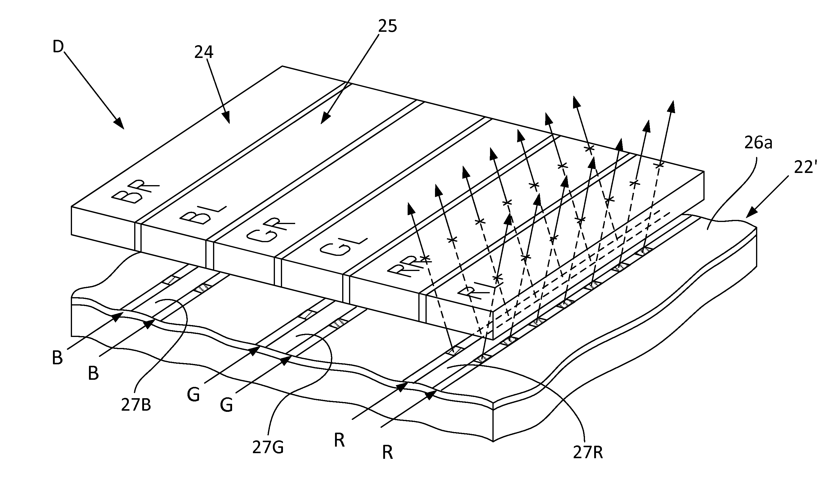
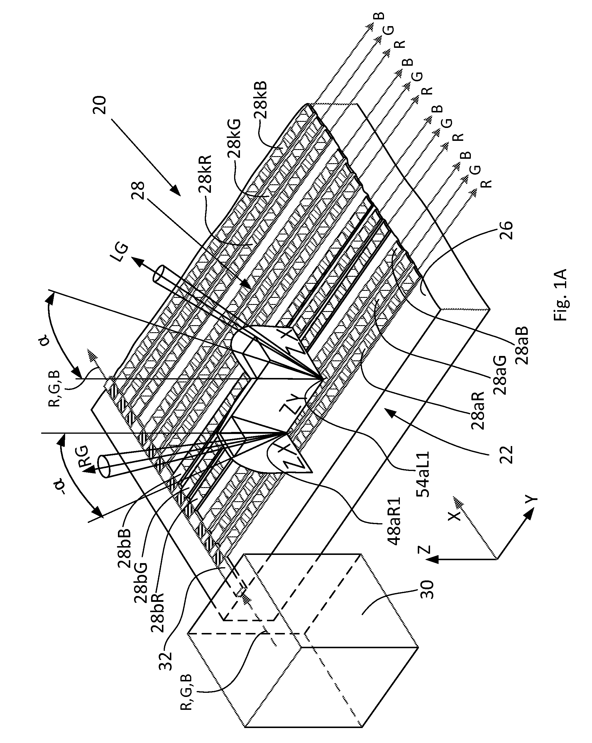
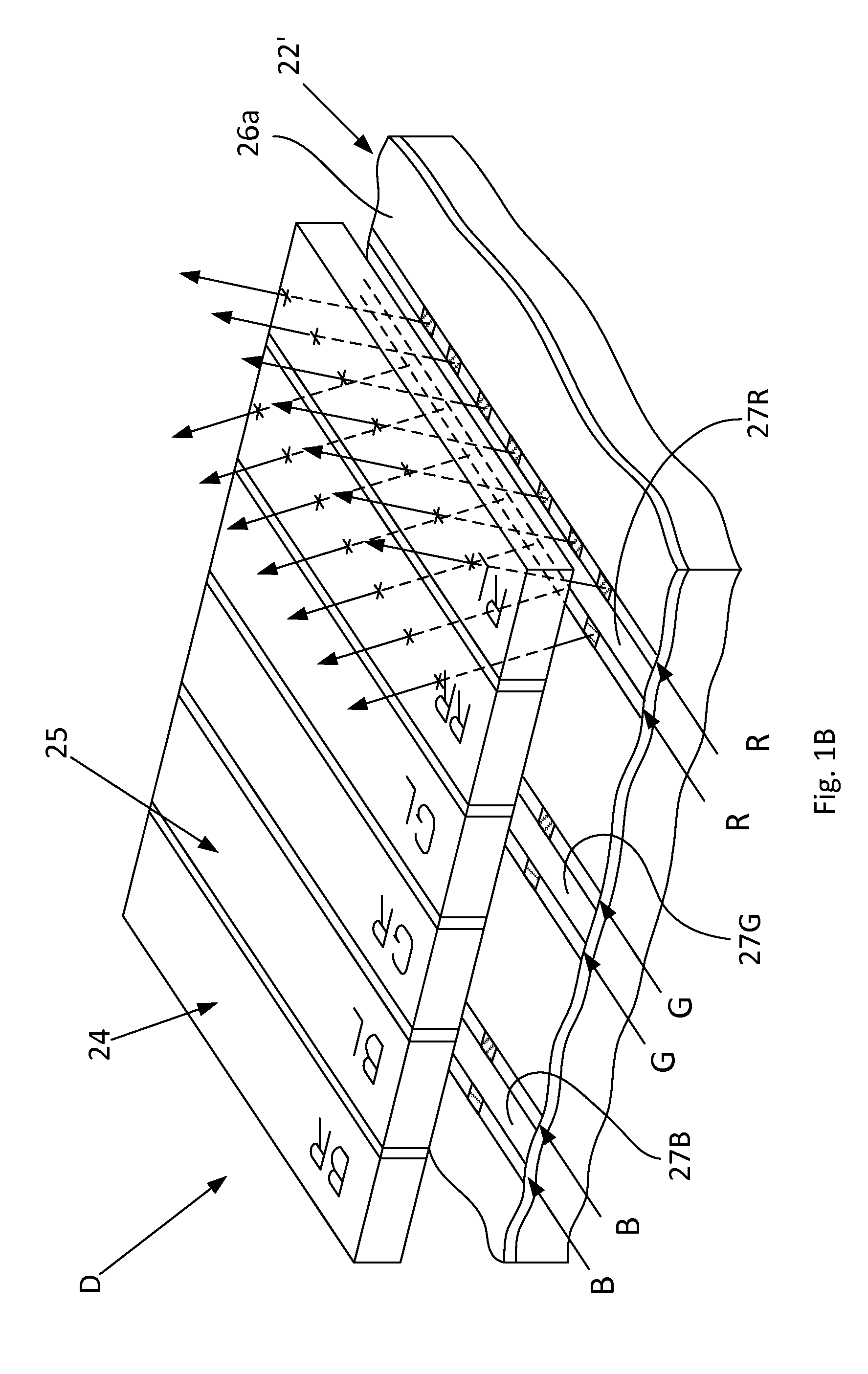
[0031]The autostereoscopic display assembly of the invention comprises a sandwich structure that consists of a lightguide plate (LGP) and a modified liquid-crystal display (MLCD), wherein the MLCD is applied onto the LGP, which is used as a source of light and a 2D-to-3D converter. FIG. 1A is a three-dimensional view of part of an LGP 20 of the autostereoscopic display assembly of the invention, and FIG. 1B is a fragmental three-dimensional view of an LGP 22′ according to another modification of the autostereoscopic display assembly D of the invention in combination with part of a modified display 24 of the invention.

[003...


PUM


Abstract

This invention relates to autostereoscopic display assemblies, in particular for hand-held devices such as tablets, i-Pads, mobile phones, etc., wherein a stereoscopic effect is achieved by forming light beams are emitted from the display at different angles and with different polarization. The display assembly comprises a sandwiched structure consisting of a light-guide panel and a modified liquid-crystal display that is applied onto the light-guide panel. The panel has on its outer surface a net of light waveguides for delivery of light from the light source and for uniform distribution of light over the entire surface of the display. The different polarizations and angular directions of the beams perceived differently by a viewer's left and right eyes are achieved by providing the light-distribution waveguides with holograms of two different types.

Description

FIELD OF THE INVENTION[0001]This invention generally relates to autostereoscopic display systems, in particular, to an autostereoscopic display that uses two light beams of different directions to achieve a stereoscopic effect. The invention may find application for displays of hand-held devices such as tablets, i-Pads, mobile phones, etc.BACKGROUND OF THE INVENTION AND DESCRIPTION OF THE PRIOR ART[0002]A three-dimensional display of images based on stereoscopy is well known in the art but in a majority of cases the stereoscopic viewing of three-dimensional (3D) images requires use of special eye wear and display equipment. Although this technique is well suitable for use in movie theaters and on TV sets with big screens, it is inconvenient for viewing 3D images on hand-held devices such as mobile phones, i-Pads, etc. For example, US Patent Application Publication 20110255160 (Myoung-jun Lee, et al) discloses 3D glasses, a 3D display apparatus, and a charging system for 3D glasses. ...

Claims


Application Information

Patent Timeline
Patent Type & Authority Applications(United States)
IPC IPC(8): G02B5/32G02B30/33
CPCG02B5/32G02B27/26G02B27/225G02B30/25G02B30/33
Inventor YANKOV, VLADIMIRGOLTSOV, ALEXANDERIVONIN, IGORKRAVTSOV, KONSTANTINVELIKOV, LEONID
Owner NANO OPTIC DEVICES
Learn More