
Apparatus for measuring performance of coherent optical receiver

a technology of optical receiver and optical receiver, which is applied in the direction of interferometric spectrometry, transmission monitoring, instruments, etc., can solve the problems of difficult to measure bandwidth and common mode rejection ratio of coherent optical receiver, and the method is limited in measuring accurate performance of coherent optical receiver

Active Publication Date: 2013-06-20
ELECTRONICS & TELECOMM RES INST
View PDF1 Cites 22 Cited by
  • Summary
  • Abstract
  • Description
  • Claims
  • Application Information

AI Technical Summary

Benefits of technology

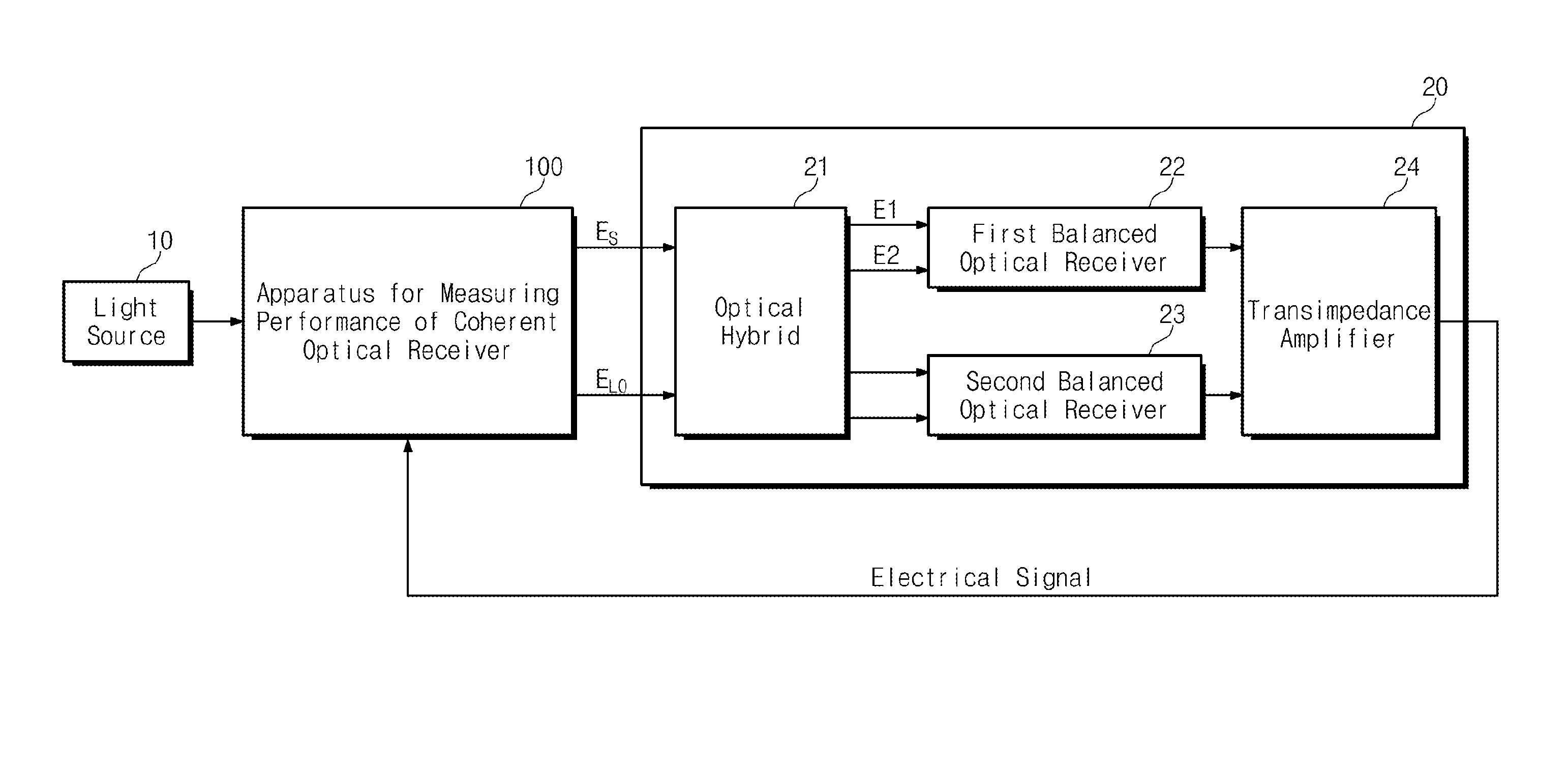
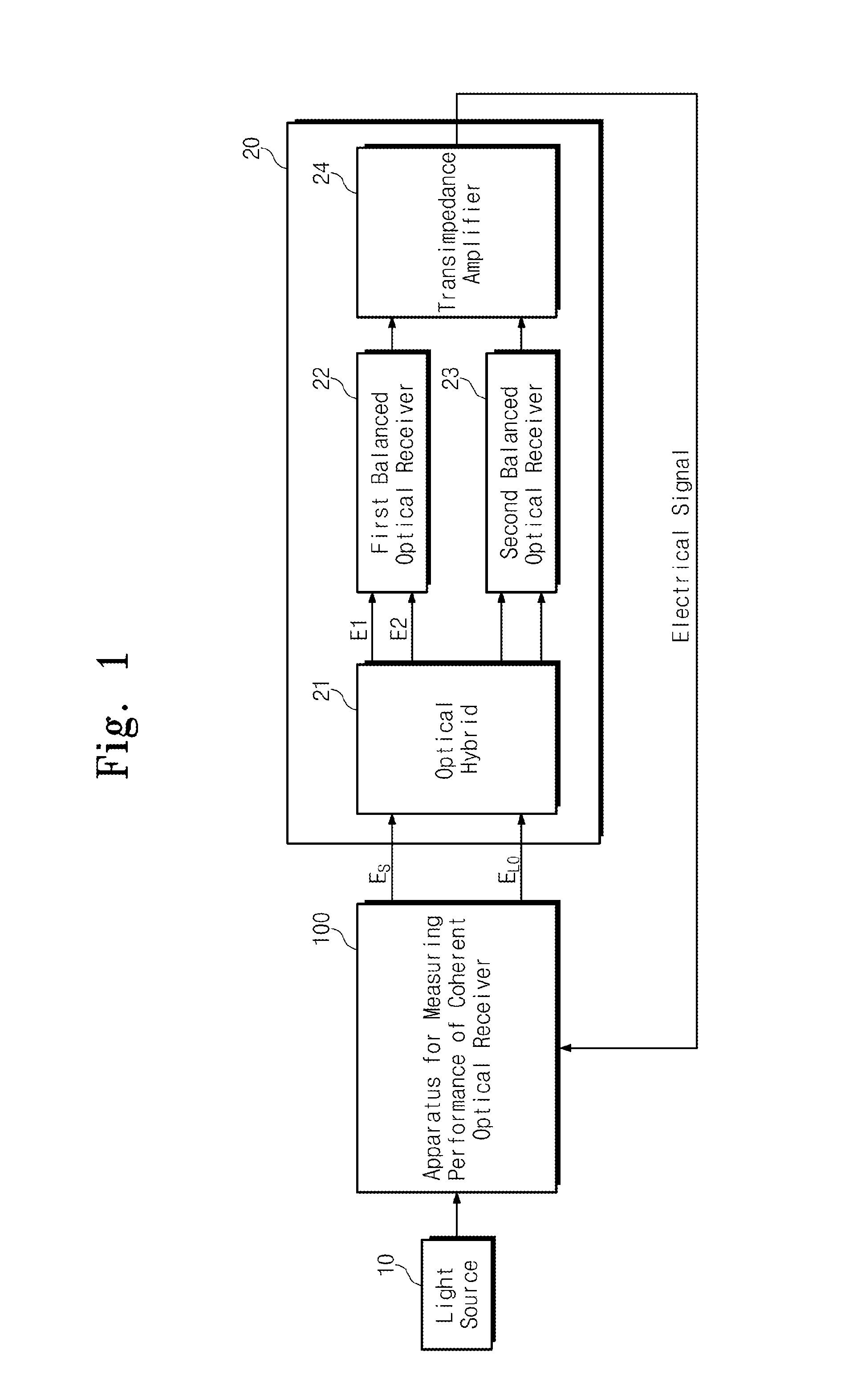
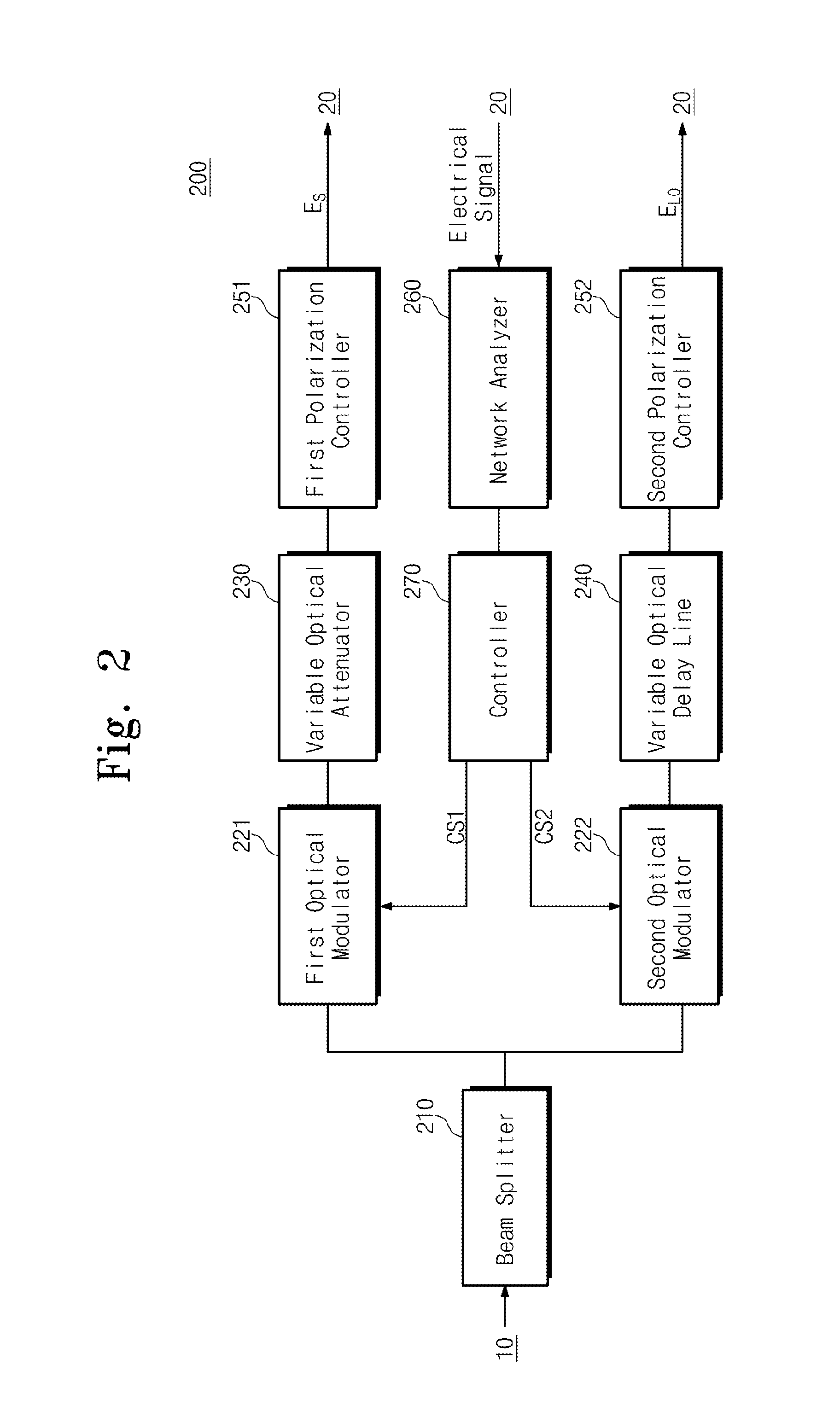
The patent describes an apparatus for measuring the performance of a coherent optical receiver. It includes a beam splitter, optical modulators, a variable optical attenuator, polarization controllers, a network analyzer, and a controller. The apparatus can measure various performance parameters such as bandwidth, common mode rejection ratio, and channel skew of the coherent optical receiver. The technical effects of the invention include improved accuracy and reliability in measuring performance parameters of coherent optical receivers.

Problems solved by technology

While it is relatively easy to measure bandwidth and common mode rejection ratio of a balanced optical receiver itself, it is not easy to measure bandwidth and common mode rejection ratio of a coherent optical receiver to which a 90-degree optical hybrid is connected.
However, this method is limited in measuring accurate performance of a coherent optical receiver because a maximum value at each frequency is assumed as a common mode component to be bused in a common mode rejection ratio through repeated tests with phase modulation.

Method used


Image

  • Apparatus for measuring performance of coherent optical receiver
  • Apparatus for measuring performance of coherent optical receiver
  • Apparatus for measuring performance of coherent optical receiver

Examples


Embodiment Construction

[0027]The advantages and features of the inventive concept and methods of achieving them will be apparent from the following exemplary embodiments that will be described in more detail with reference to the accompanying drawings. It should be noted, however, that the inventive concept is not limited to the following exemplary embodiments, and may be implemented in various forms. Accordingly, the exemplary embodiments are provided only to disclose examples of the inventive concept and to let those skilled in the art understand the nature of the inventive concept.

[0028]There is a method for measuring bandwidth and common mode rejection ratio of a balanced optical receiver, not a coherent optical receiver. In this method, an optical signal is input to one of two input ports to measure a common mode component of the balanced optical receiver and an optical signal is input to both the two input ports to measure a differential mode component. This method can be used to measure common mode...


PUM


Abstract

An apparatus for measuring performance of a coherent optical receiver includes a beam splitter splitting light into first and second paths, a first optical modulator modulating the first path light, a variable optical attenuator controlling an optical power of the first optical modulator, a first polarization controller transmitting a signal controlling polarization of an output of the variable optical attenuator to the coherent optical receiver, a second optical modulator modulating the second path light, a variable optical delay line delaying time of an output of the second optical modulator, a second polarization controller transmitting a signal controlling polarization of an output of the variable optical delay line to the coherent optical receiver, a network analyzer measuring performance of the coherent optical receiver and controlling the optical modulators, and a controller transmitting a control signal to the optical modulators.

Description

CROSS-REFERENCE TO RELATED APPLICATIONS[0001]This US non-provisional patent application claims priority under 35 USC §119 to Korean Patent Application No. 10-2011-0134352, filed on Dec. 14, 2011, the entirety of which is hereby incorporated by reference.BACKGROUND OF THE INVENTION[0002]The present general inventive concept relates to apparatuses for measuring performance of a coherent optical receiver and, more particularly, to an apparatus for measuring performance of a coherent optical receiver which measures a common mode rejection ratio.[0003]With the continuous increase in communication capacity, a direct detection method has been conventionally used in an optical communication system of 100 Gb / s or more to detect an optical signal. However, a coherent detection method is increasingly used in recent years. The coherent detection method may improve spectral efficiency to make ultrahigh-speed transmission available and compensate transmission quality degradation through digital s...

Claims


Application Information

Patent Timeline
Patent Type & Authority Applications(United States)
IPC IPC(8): H04B10/08
CPCH04B10/0799H04B10/614G01J3/45G01R31/00
Inventor YOUN, CHUN JUCHOE, JOONG-SEONKIM, JONG-HOIKIM, DUK JUNKWON, YONG-HWANNAM, EUN SOO
Owner ELECTRONICS & TELECOMM RES INST
Learn More