Counter operation in a state machine lattice

Active Publication Date: 2013-06-20
MICRON TECH INC
View PDF1 Cites 44 Cited by
  • Summary
  • Abstract
  • Description
  • Claims
  • Application Information

AI Technical Summary

Problems solved by technology

In the field of computing, pattern recognition tasks are increasingly challenging.
However, recognizing a pattern m

Method used


Image

  • Counter operation in a state machine lattice
  • Counter operation in a state machine lattice
  • Counter operation in a state machine lattice

Examples


Embodiment Construction

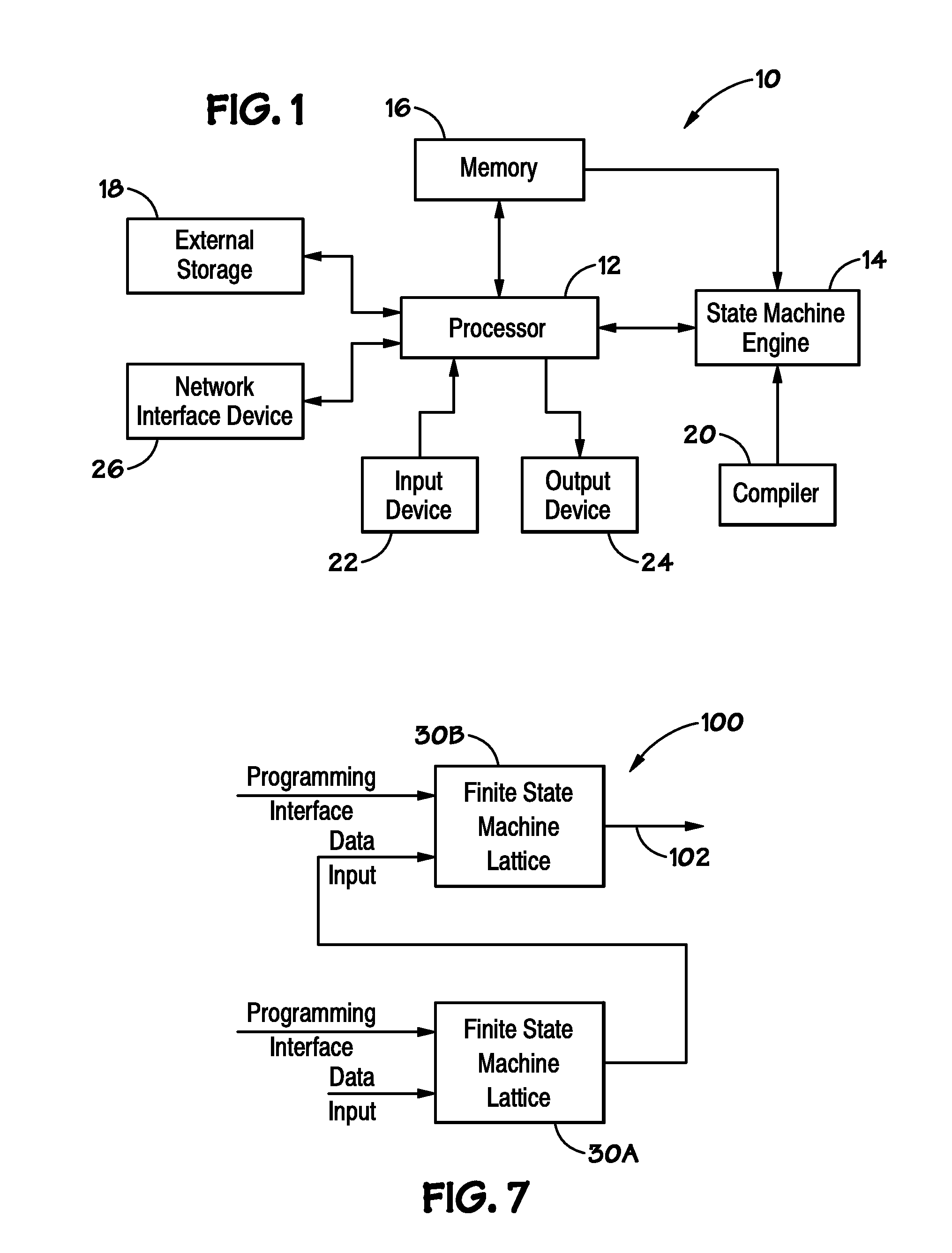
[0017]Turning now to the figures, FIG. 1 illustrates an embodiment of a processor-based system, generally designated by reference numeral 10. The system 10 may be any of a variety of types such as a desktop computer, laptop computer, pager, cellular phone, personal organizer, portable audio player, control circuit, camera, etc. The system 10 may also be a network node, such as a router, a server, or a client (e.g., one of the previously-described types of computers). The system 10 may be some other sort of electronic device, such as a copier, a scanner, a printer, a game console, a television, a set-top video distribution or recording system, a cable box, a personal digital media player, a factory automation system, an automotive computer system, or a medical device. (The terms used to describe these various examples of systems, like many of the other terms used herein, may share some referents and, as such, should not be construed narrowly in virtue of the other items listed.)

[0018...


PUM


Abstract

Disclosed are methods and devices, among which is a device that includes a finite state machine lattice. The lattice may include a counter suitable for counting a number of times a programmable element in the lattice detects a condition. The counter may be configured to output in response to counting the condition was detected a certain number of times. For example, the counter may be configured to output in response to determining a condition was detected at least (or no more than) the certain number of times, determining the condition was detected exactly the certain number of times, or determining the condition was detected within a certain range of times. The counter may be coupled to other counters in the device for determining high-count operations and/or certain quantifiers.

Description

BACKGROUND[0001]1. Field of Invention[0002]Embodiments of the invention relate generally to electronic devices and, more specifically, in certain embodiments, to parallel finite state machines for pattern-recognition.[0003]2. Description of Related Art[0004]In the field of computing, pattern recognition tasks are increasingly challenging. Ever larger volumes of data are transmitted between computers, and the number of patterns that users wish to detect is increasing. For example, spam and malware are often detected by searching for patterns in a data stream, e.g., particular phrases or pieces of code. The number of patterns increases with the variety of spam and malware, as new patterns may be implemented to search for new variants.[0005]Recognizing a pattern may often involve detecting various conditions indicative of the pattern. It may also be useful to count the number of times a condition(s) is(are) detected. Counters may be implemented to count a number of times a condition is...

Claims


Application Information

Patent Timeline
IPC IPC(8): G06F15/76G06F9/02
CPCG06F15/82G06F21/567G05B19/045G06F2207/025G06N5/047G06F9/4498H03K19/17724H03K19/17748
Inventor NOYES, HAROLD BBROWN, DAVID R.GLENDENNING, PAUL
Owner MICRON TECH INC
Why Eureka
Try Eureka