Hydraulic power steering system

Inactive Publication Date: 2013-06-27
JTEKT CORP
View PDF5 Cites 6 Cited by
  • Summary
  • Abstract
  • Description
  • Claims
  • Application Information

AI Technical Summary

Benefits of technology

[0008]The invention provides a hydraulic power steering system that is able to avoid reduction in response of

Problems solved by technology

As a result, motor torque of the valve driving motor becomes insufficient, leading to reduction in response

Method used


Image

  • Hydraulic power steering system
  • Hydraulic power steering system
  • Hydraulic power steering system

Examples


Embodiment Construction

[0019]Hereinafter, embodiments of the invention will be described with reference to the accompanying drawings.

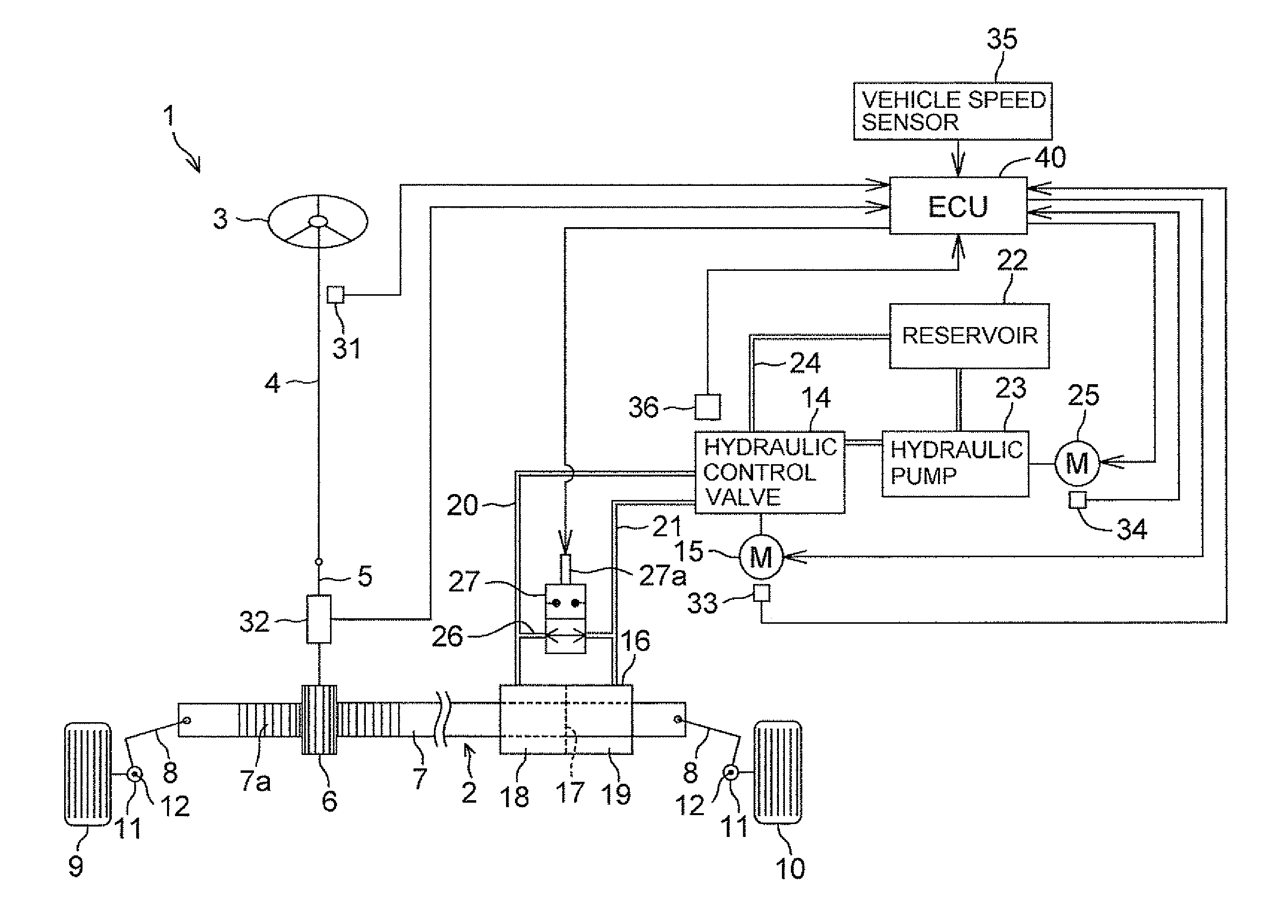
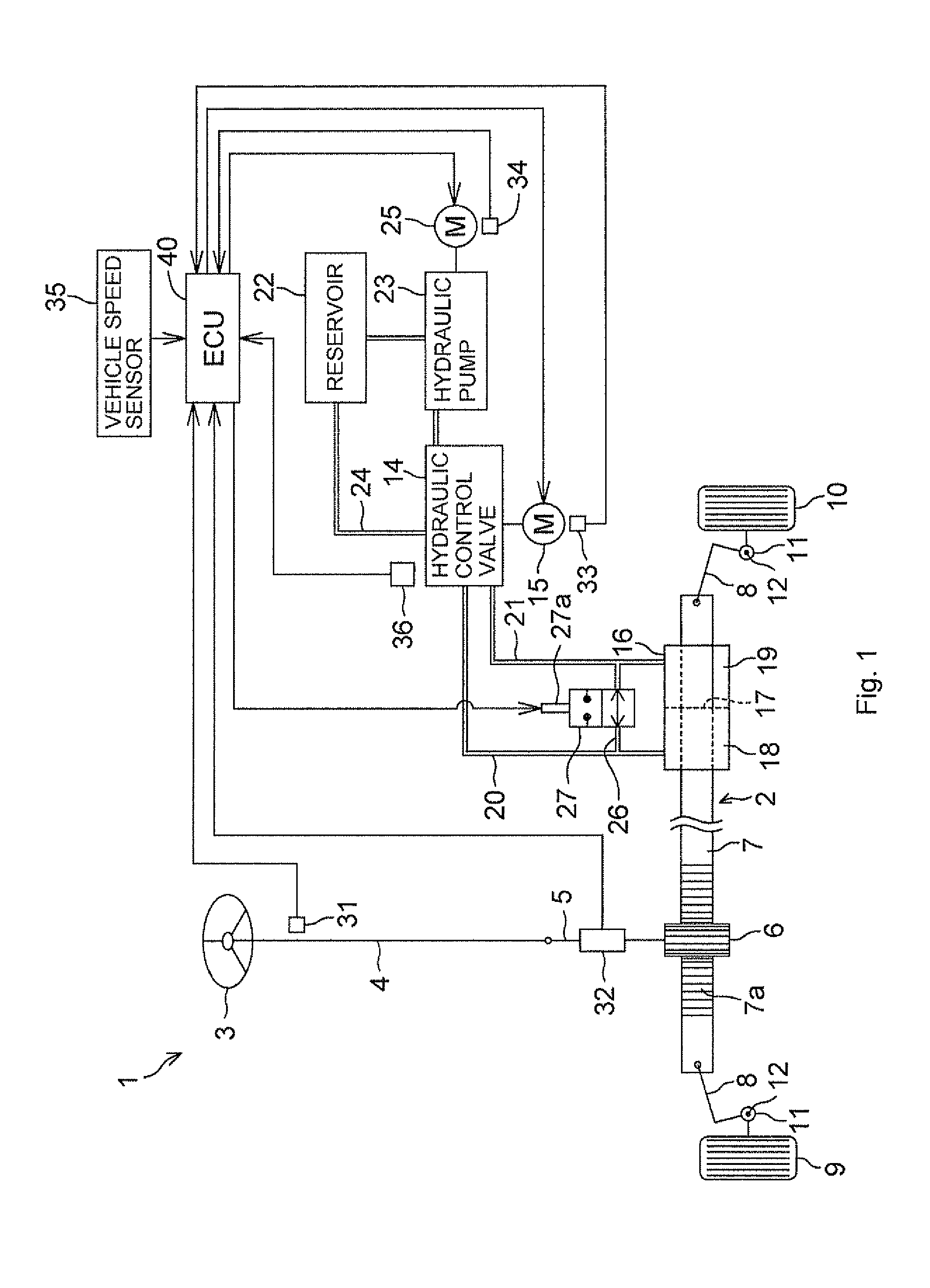
[0020]FIG. 1 shows the schematic configuration of a hydraulic power steering system 1 according to an embodiment of the invention. The hydraulic power steering system 1 applies steering assist force to a steering mechanism 2 of a vehicle. The steering mechanism 2 includes a steering wheel 3, a steering shaft 4, a pinion shaft 5 and a rack shaft 7. The steering wheel 3 serves as a steering member, and is operated by a driver in order to steer the vehicle. The steering shaft 4 is coupled to the steering wheel 3. The pinion shaft 5 is coupled to the distal end portion of the steering shaft 4, and has a pinion gear 6. The rack shaft 7 has a rack 7a that is in mesh with the pinion gear 6, and serves as a steered shaft that extends in the lateral direction of the vehicle.

[0021]Tie rods 8 are coupled to respective ends of the rack shaft 7. The tie rods 8 are coupled to knuckle arms...


PUM


Abstract

When an ECU is powered on, an overall control unit determines whether a temperature detected by a temperature sensor is lower than or equal to a predetermined temperature. When it is determined that the detected temperature is lower than or equal to the predetermined temperature, the overall control unit provides a second operation start command for operating a valve driving motor control unit in a rotation direction alternately switching mode, to the valve driving motor control unit. When the valve driving motor control unit receives the second operation start command from the overall control unit, the valve driving motor control unit starts operating in the rotation direction alternately switching mode.

Description

INCORPORATION BY REFERENCE / RELATED APPLICATION[0001]This application claims priority to Japanese Patent Application No. 2011-283727 filed on Dec. 26, 2011 the disclosure of which, including the specification, drawings and abstract, is incorporated herein by reference in its entirety.BACKGROUND OF THE INVENTION[0002]1. Field of the Invention[0003]The invention relates to a hydraulic power steering system.[0004]2. Discussion of Background[0005]There is a conventional hydraulic power steering system that generates steering assist force by supplying hydraulic fluid from a hydraulic pump to a power cylinder, which is coupled to a steering mechanism of a vehicle, via a hydraulic control valve. In a commonly-used hydraulic power steering system, a hydraulic control valve is mechanically coupled to a steering member, such as a steering wheel, via a steering shaft, and the opening degree of the hydraulic control valve is controlled in response to an operation of the steering member.[0006]Jap...

Claims


Application Information

Patent Timeline
IPC IPC(8): B62D5/09
CPCB62D5/09B62D5/065
Inventor SAKAMAKI, MASAHIKOIZUTANI, KEISUKE
Owner JTEKT CORP
Why Eureka
Try Eureka