Image signal processing apparatus, image scanning apparatus and method for processing image signal

a signal processing and image signal technology, applied in the field of image signal processing apparatus and a processing method of image signal, can solve the problems of difficult control of the phase easy noise of the loop filter signal, and mixed spectrum noise in the image signal, so as to achieve the effect of filtering out nois

Inactive Publication Date: 2013-06-27
RICOH KK
View PDF7 Cites 13 Cited by
  • Summary
  • Abstract
  • Description
  • Claims
  • Application Information

AI Technical Summary

Benefits of technology

[0011]It is a general object of the present invention to provide an image signal processing apparatus and a method for processing an image signal that can filter out the noise which is generated by the fluctuation of the clock signal more effectively than the conventional image signal processing apparatuses. The noise is included in the image signal obtained by CCD or the like which operates based on the clock signal that has been subjected to spread spectrum modulation.

Problems solved by technology

Conventional image scanning apparatuses have a problem in that EMI (Electromagnetic Interference) which has a peak at a specific frequency is caused by a clock signal that is provided into a photoelectric conversion element such as CCD or the like.
However, there is a problem in that spread spectrum noise is mixed into the image signal obtained by the CCD when the clock signal is generated by the SSCG.
However, according to the techniques shown in FIGS. 1 and 2, there are problems as described below.
It is difficult to control the phase of the loop filter signal.
The loop filter signal is susceptible to the noise, since the amplitude of the loop filter signal is relatively small.

Method used


Image

  • Image signal processing apparatus, image scanning apparatus and method for processing image signal
  • Image signal processing apparatus, image scanning apparatus and method for processing image signal
  • Image signal processing apparatus, image scanning apparatus and method for processing image signal

Examples


Embodiment Construction

[0029]In the following, embodiments of the present invention will be described with reference to the accompanying drawings.

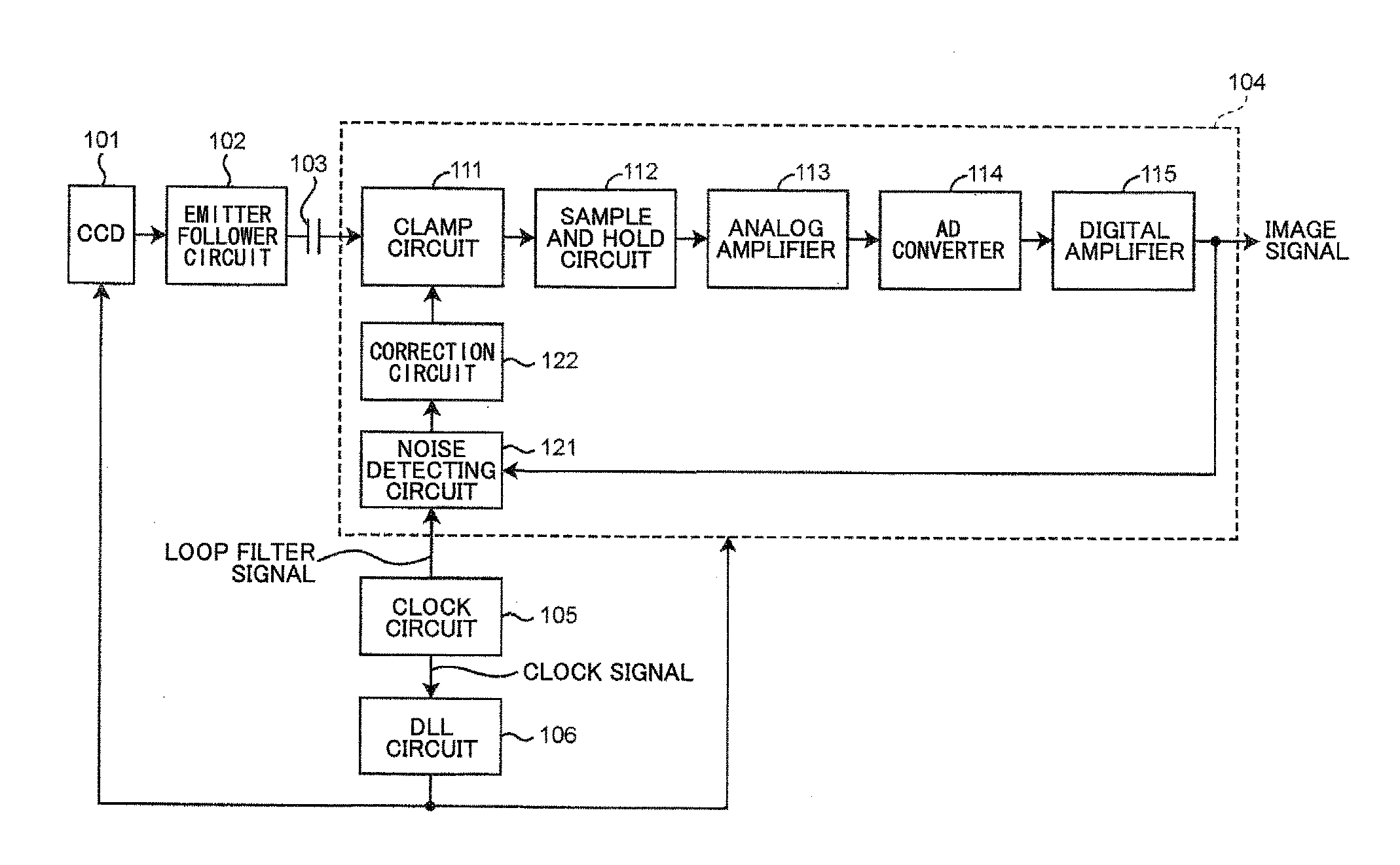
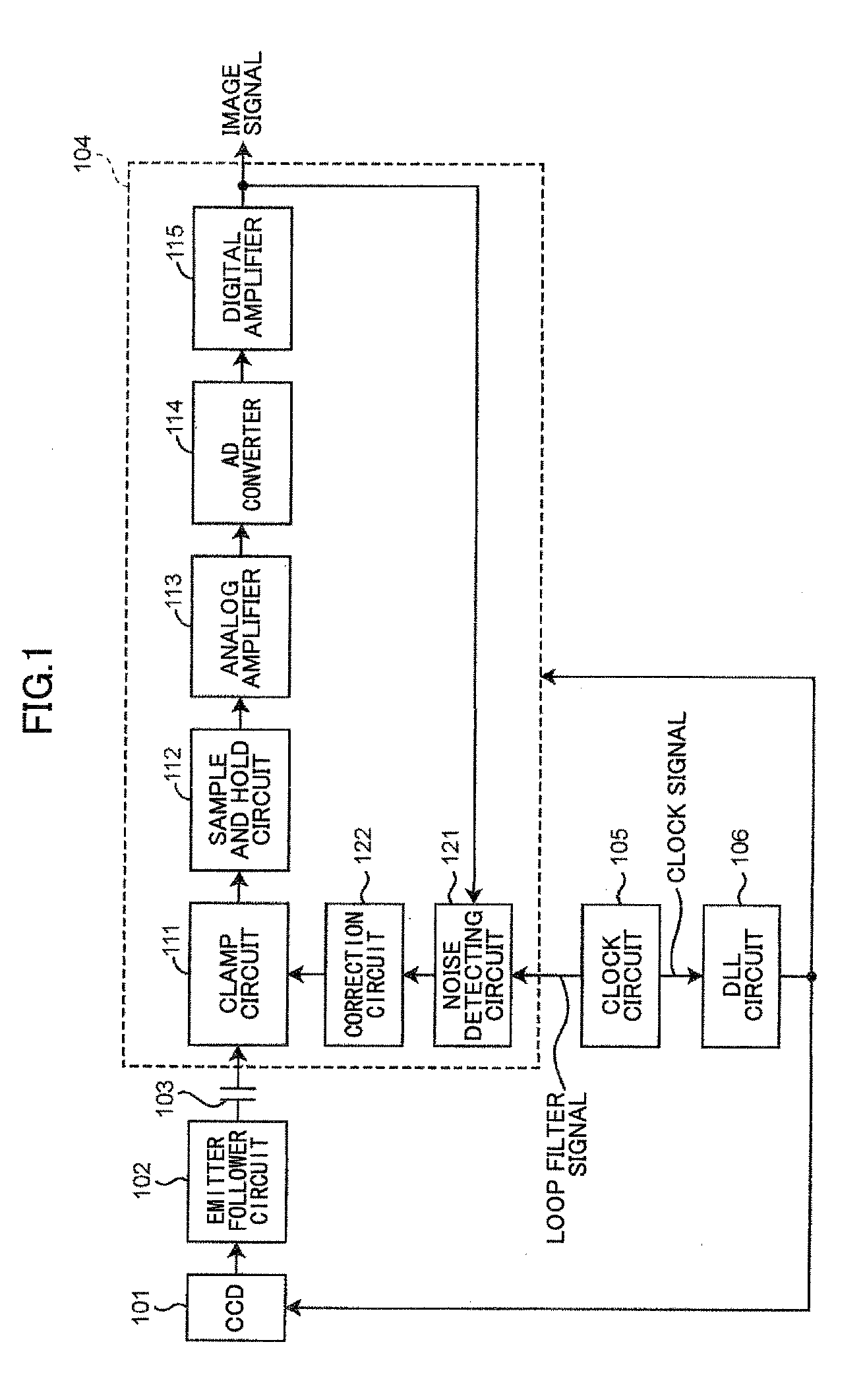
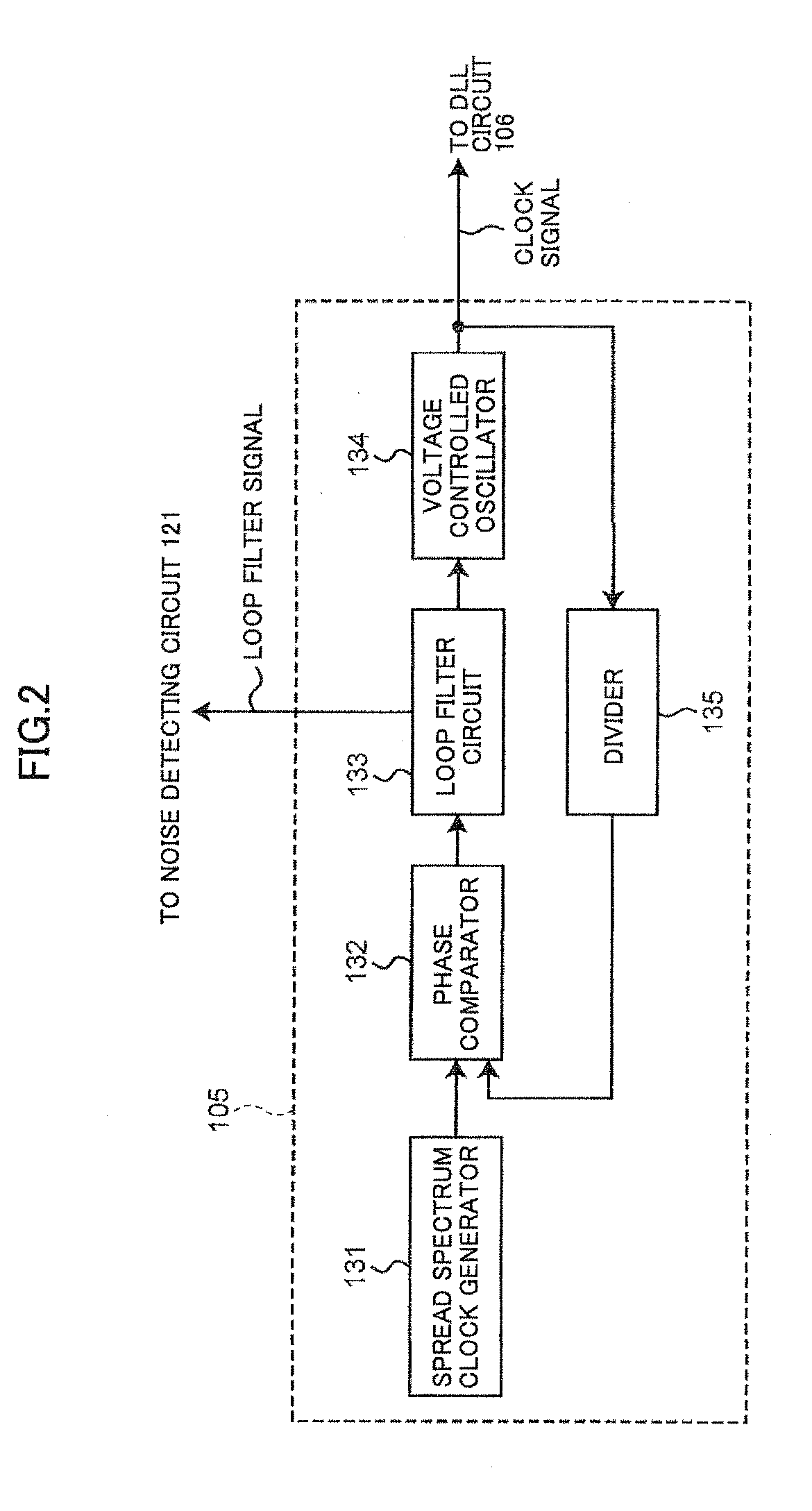
[0030]FIG. 3 is a block diagram showing a configuration of an image scanning apparatus according to an embodiment of the present invention. FIG. 4 is a block diagram showing a detailed configuration of a clock circuit 24.

[0031]The image scanning apparatus of the present embodiment includes a signal processing circuit 4 which filters out noise (spread spectrum noise) generated by fluctuation of a clock signal. The noise is included in an image signal obtained by a CCD 1 which operates based on a clock signal that has been subjected to spread spectrum modulation. The image scanning apparatus of the present embodiment can reduce the peak level of the EMI which has the peak at a specific frequency by dispersing the energy of the EMI in a similar manner to the conventional image scanning apparatus which includes the SSCG. The image scanning apparatus of the present e...


PUM


Abstract

A signal processing circuit 4 includes a clock circuit 24 which generates a clock signal which has been subjected to spread spectrum modulation and supplies the clock signal to a photoelectric conversion element; a AD converter 15 which performs AD conversion on an image signal obtained by the photoelectric conversion element; a noise detecting circuit 21 which detects a noise amplitude of a noise signal that is caused by the spread spectrum modulation of the clock signal and is included in the image signal which has been AD converted; and an analog correction circuit 23 and an digital correction circuit 22 that calculate a correction factor based on the noise amplitude, generate a correction signal by multiplying the digital modulation signal by the correction factor, and superimpose the correction signal onto the image signal at an input side or an output side of the AD converter.

Description

TECHNICAL FIELD[0001]The present invention generally relates to an image signal processing apparatus and a method for processing an image signal that filter out noise generated by fluctuation of a clock signal. The noise is included in an image signal obtained by a CCD or the like which operates based on the clock signal that has been subjected to spread spectrum modulation. The present invention further relates to an image scanning apparatus which includes the image signal processing apparatus.[0002]2. Background Art[0003]Conventional image scanning apparatuses have a problem in that EMI (Electromagnetic Interference) which has a peak at a specific frequency is caused by a clock signal that is provided into a photoelectric conversion element such as CCD or the like. A spread spectrum clock generator (SSCG) has been used in order to solve the problem. The SSCG disperses the energy of the EMI which has the peak at the specific frequency and reduces the peak level of the EMI by modula...

Claims


Application Information

Patent Timeline
Patent Type & Authority Applications(United States)
IPC IPC(8): H04N5/217
CPCH04N1/409H04N5/3577H04N1/40056H04N5/217H04N5/3765H04N25/617H04N25/745H04N23/81
Inventor MIYOSHI, YUUYAKANNO, TOHRU
Owner RICOH KK
Why Eureka
Try Eureka