Illumination system and wavelength-transforming device thereof

a wavelength-transforming device and a technology of a system are applied in the field of systems to eliminate the drawbacks of higher price and weight and worse performance, and achieve the effects of reducing the cost and difficulty of fabricating, avoiding the effect of long manufacturing time and avoiding the effect of reducing the cost and difficulty

Active Publication Date: 2013-06-27
DELTA ELECTRONICS INC
View PDF5 Cites 14 Cited by
  • Summary
  • Abstract
  • Description
  • Claims
  • Application Information

AI Technical Summary

Benefits of technology

[0010]The present invention provides an illumination system and a wavelength-transforming device thereof in order to eliminate the drawbacks caused by the higher price and weight and the worse performance in high working temperature of the red phosphor agent (e.g. high fabricating cost and difficulty, long fabricating time, low brightness and illuminance decay).
[0011]The present invention also provides an illumination system and a wavelength-transforming device thereof. The illumination system utilizes a single solid-state light-emitting element and a single wavelength-transforming device having a single segment in replace of conventional red phosphor agent or conventional red solid-state light-emitting element to simplify the fabricating processes, reduce the fabricating cost, be used in high working temperature, and further improve the color purity and image quality.
[0012]The present invention further provides an illumination system and a wavelength-transforming device thereof Via the wavelength-transforming device, a first color light in a first waveband region is excited and transformed as a second color light in a wider waveband region, which is the second waveband region. As a result, the illumination system emits red light without using a red phosphor agent, so that the luminance and illuminance decay caused by the characteristic of the red phosphor agent when the driving current of the blue light laser rises is avoided.

Problems solved by technology

However, the red phosphor agent still has some drawbacks.
For example, the cost of the red phosphor agent is higher and the performance in high working temperature is worse.
Nevertheless, not only the overall fabricating cost, but also the fabricating time and difficulty of the illumination system will be increased due to the higher price, the higher weight and the worse performance in high working temperature of the red phosphor agent, which is coated on a segment of the phosphor wheel of the illumination system.
Therefore, the luminance and the illuminance will be too low, such that the whole brightness cannot be integrated effectively, and further the sharpness and the contrast of color will be affected.

Method used


Image

  • Illumination system and wavelength-transforming device thereof
  • Illumination system and wavelength-transforming device thereof
  • Illumination system and wavelength-transforming device thereof

Examples


Embodiment Construction

[0026]The present invention will now be described more specifically with reference to the following embodiments. It is to be noted that the following descriptions of preferred embodiments of this invention are presented herein for purpose of illustration and description only. It is not intended to be exhaustive or to be limited to the precise form disclosed.

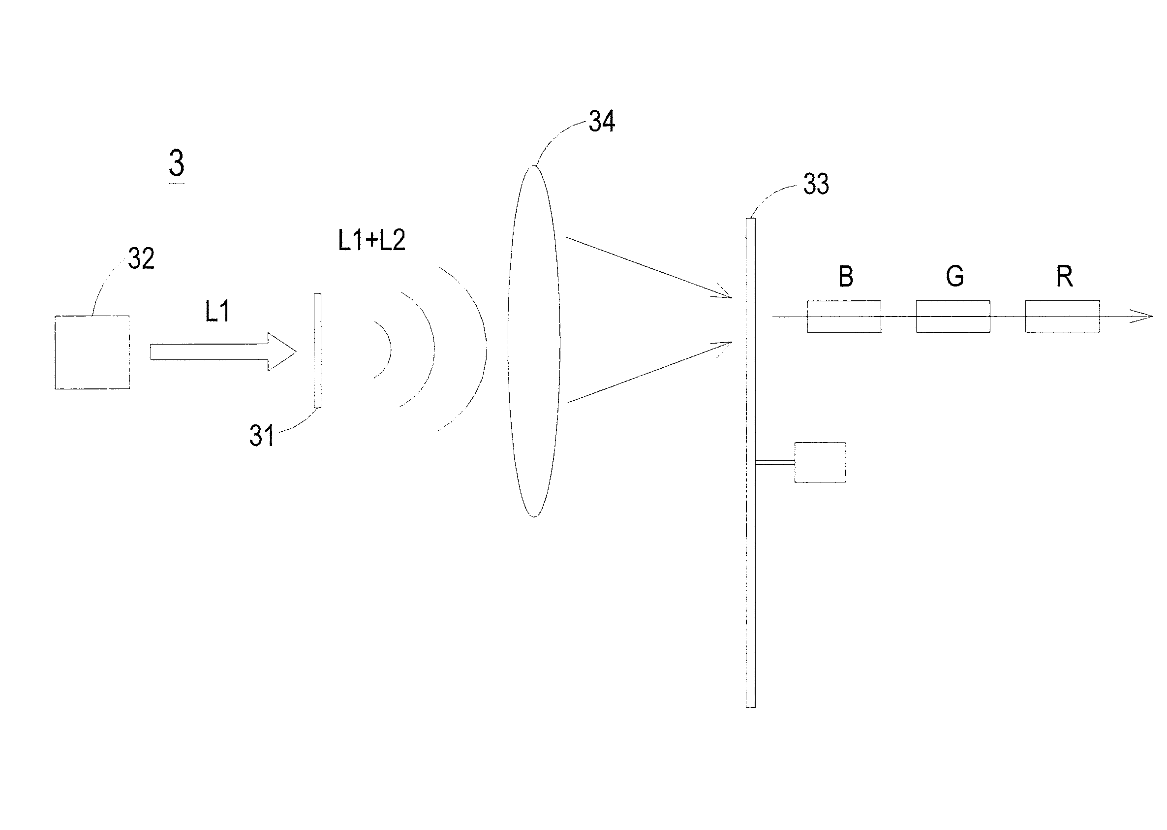
[0027]Please refer to FIGS. 3A, 3B and 3C. FIG. 3A schematically illustrates the configuration of an illumination system according to an embodiment of the present invention. FIG. 3B schematically illustrates the configuration of a wavelength-transforming device as shown in FIG. 3A. FIG. 3C schematically illustrates the configuration of a filter wheel as shown in FIG. 3A. The illumination system 3 of the present invention comprises a wavelength-transforming device 31, a solid-state light-emitting element 32 and a filter wheel 33 and is not limited to a transmissive illumination system. The wavelength-transforming device 31 is for ...


PUM


Abstract

An illumination system includes a wavelength-transforming device, a solid-state light-emitting element and a filter wheel. The wavelength-transforming device comprises a segment and a wavelength-transforming element disposed on the segment. The solid-state light-emitting element emits first color light in first waveband region to the wavelength-transforming device. The filter wheel is disposed on one side of the wavelength-transforming device for filtering lights via rotating. The first color light is excited as second color light in second waveband region by the wavelength-transforming device, so that the second color light is outputted with the rest of the first color light. The first and second color lights are transmitted through the filter wheel, such that three primary color lights are sequentially projected. The present invention achieves the advantages of reducing cost, simplifying fabricating processes, being available for high working temperature, and further improving image quality without using red phosphor agent or red solid-state light-emitting element.

Description

CROSS-REFERENCE TO RELATED APPLICATION[0001]This application claims the benefit of U.S. Provisional Application No. 61 / 580,380 filed on Dec. 27, 2011, and entitled “SOLID STATE REMOTE WHITE LIGHT SOURCE FOR PROJECTION”, the entirety of which is hereby incorporated by reference.FIELD OF THE INVENTION[0002]The present invention relates to a system, and more particularly to an illumination system and a wavelength-transforming device thereof.BACKGROUND OF THE INVENTION[0003]In recent years, kinds of projectors are widely used in schools, homes and business occasions in order to amplify image signals provided by an image signal source and then display on a projection screen. For the purpose of reducing the power consumption and the size of devices, a solid-state light-emitting element is employed in the illumination system of current projector to replace the conventional high intensity discharge (HID) lamp.[0004]Generally, the illumination system of the projector should emit three primar...

Claims


Application Information

Patent Timeline
Patent Type & Authority Applications(United States)
IPC IPC(8): F21V9/00F21V13/02F21V9/16F21V9/40
CPCH04N9/3114H04N9/3158H04N9/3161G03B33/06F21V9/16F21V13/02G03B21/204F21V9/00F21V9/30
Inventor CHANG, KEH-SU
Owner DELTA ELECTRONICS INC
Why Eureka
Try Eureka