Image stabilization apparatus, control method therefor, optical apparatus and imaging apparatus

Active Publication Date: 2013-06-27
CANON KK
View PDF1 Cites 22 Cited by
  • Summary
  • Abstract
  • Description
  • Claims
  • Application Information

AI Technical Summary

Benefits of technology

[0014]The present invention has been made in consideration of the above situation, and is to obtain images with a high level of stabilization accur

Problems solved by technology

However, when shooting at close ranges, shooting at a high magnification ratio, and so on, image degradation caused by what are known as “translational shakes” (parallel shakes), which act in the translational or vertical direction relative to the optical axis of the camera and cannot be detected solely by an angular velocity sensor, cannot be ignored.
During close range shooting, because a significant error occurs in the correction amount due to the difference in magnification ratio, if the vibration correction amount is not adjusted for each object distance, it is not possible to perform good vibration correction on the entire screen.
Specifically, in the case where sufficient vibration correction is performed on a main object, the distance to which is 10 cm, its background (for example, the object distance is 1 m) is not sufficiently corrected, instead, the image blur may become worse (overcorrection).
Particularly when shooting a movi

Method used


Image

  • Image stabilization apparatus, control method therefor, optical apparatus and imaging apparatus
  • Image stabilization apparatus, control method therefor, optical apparatus and imaging apparatus
  • Image stabilization apparatus, control method therefor, optical apparatus and imaging apparatus

Examples


Example

First Embodiment

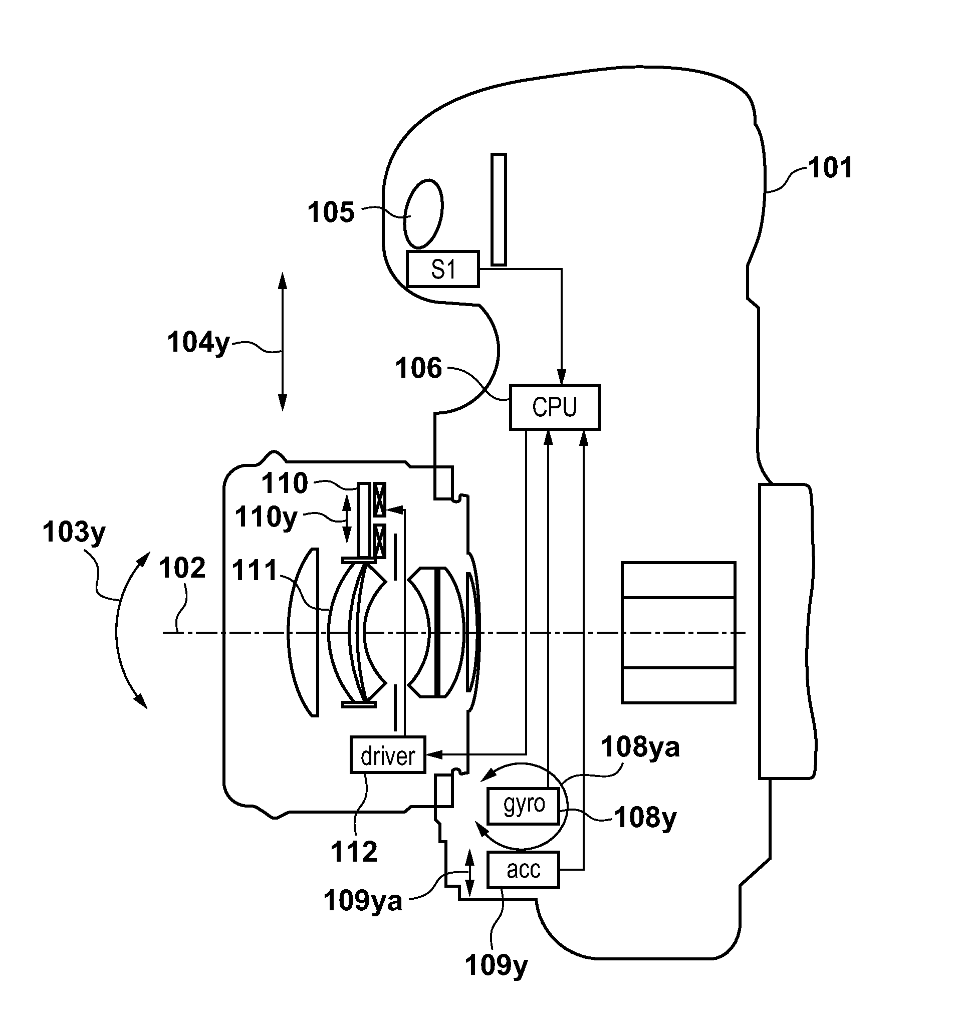
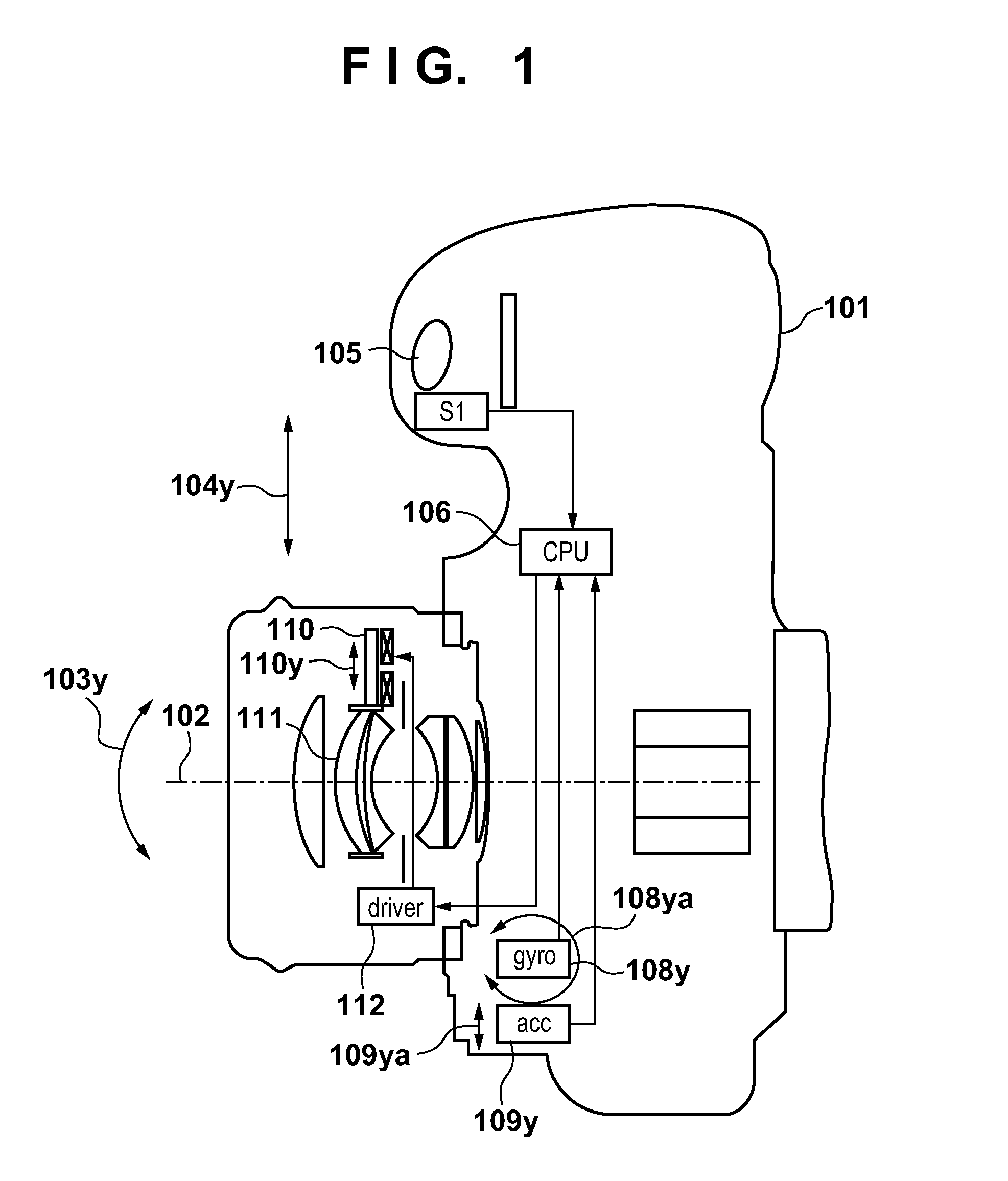
[0034]FIGS. 1 and 2 are general diagrams illustrating the functional configuration of a camera 101 embodying an image stabilization apparatus according to a first embodiment of the present invention, viewed from above and from the side, respectively. A stabilization system provided in this camera 101 compensates shakes indicated by arrows 103p and 103y relative to an optical axis 102 (called “rotational shakes” hereinafter) and shakes indicated by arrows 104p and 104y relative to the optical axis 102 (called “translational shakes” hereinafter).

[0035]The camera 101 includes a release switch 105, a camera CPU 106, an image sensor 107, and angular velocity sensors 108p and 108y that detect rotational shakes indicated by arrows 108pa and 108ya, respectively. The camera 101 further includes acceleration sensors 109p and 109y that detect translational shakes indicated by arrows 109pa and 109ya, respectively, using a different method than the angular velocity sensors 108p a...

Example

Second Embodiment

[0076]A second embodiment of the present invention will be described next. The second embodiment is different from the first embodiment in the following points.

[0077]In the first embodiment, the correction amount is adjusted by multiplying the translational shake correction amount by the correction gain K according to the in-focus area of the main object. In the second embodiment, rather than performing multiplication using the correction gain K after the translational shake correction amount has been calculated, the translational shake correction amount is adjusted by calculating the magnification ratio from the zoom and object distance information according to the in-focus area of the main object and multiplying the magnification ratio by the correction gain K. Also, in the first embodiment, only the translational shake correction amount is multiplied by the correction gain, whereas in the second embodiment, the rotational shake correction amount is also adjusted ...

Example

Third Embodiment

[0084]A third embodiment of the present invention will be described next. The third embodiment is different from the first and second embodiments in the following points.

[0085]In the first embodiment, adjustment is performed by multiplying the translational shake correction amount by the correction gain K according to the in-focus area of the main object, and in the second embodiment, the rotational shake correction amount and the translational shake correction amount are adjusted by setting the correction gains Ka and Kb for the magnification ratio according to the in-focus area of the main object. In the third embodiment, the correction gain K is determined according to the in-focus area and magnification ratio information, rather than according to only the in-focus area.

[0086]FIG. 12 is a diagram showing a correction gain according to the in-focus area and the magnification ratio. Reference numeral 1001 indicates correction gain characteristics according to the in...


PUM


Abstract

An image stabilization apparatus, having a vibration correction unit that corrects image blur due to vibrations, detects an angular velocity of vibrations with a first vibration detection unit, calculates a rotational shake correction amount based on an output from the first vibration detection unit, detects vibrations with a second vibration detection unit, calculates a correction value from the outputs of the first and second vibration detection units, calculates a translational shake correction amount based on the correction value and the output of the first vibration detection unit, and drives the vibration correction unit based on at least one of the rotational or translational shake correction amounts. The image stabilization apparatus changes the translational shake correction amount to a smaller value when a main object accounts for a smaller proportion of an entire screen.

Description

BACKGROUND OF THE INVENTION[0001]1. Field of the Invention[0002]The present invention relates to an image stabilization apparatus that compensate image blur (image degradation) caused by shakes such as hand shakes, and relates to a control method for such an image stabilization apparatus, an optical apparatus, and an imaging apparatus.[0003]2. Description of the Related Art[0004]At present, cameras provided with image stabilization apparatuses that prevent image blur caused by hand shakes and are configured with, for example, a shake compensation unit, a driving unit, and a shake detection unit are in commercial production, and as a result, user-caused shooting mistakes are decreasing.[0005]Camera shake caused by hand shakes of a user is usually within a frequency range of 1 to 10 Hz. In order to capture a blur-free photo even if such hand shakes occurs at the time of shutter release, a unit is conventionally provided that detects camera vibrations caused by hand shake and moves a l...

Claims


Application Information

Patent Timeline
IPC IPC(8): G03B15/00
CPCH04N5/23258H04N5/23267G03B2217/005G03B5/00G03B2205/0015G03B15/00H04N23/6812H04N23/683G02B27/646G03B17/02G03B5/02G03B2205/0007H04N23/67H04N23/681H04N23/687
Inventor MIYAZAWA, HITOSHI
Owner CANON KK
Why Eureka
Try Eureka