Sandwich laminate and manufacturing method

a manufacturing method and laminate technology, applied in the field of sandwich laminate, can solve the problems of not common thermoplastic materials, difficult to heat up materials, and difficult to recycle, etc., and achieve the effect of convenient recycling

a manufacturing method and laminate technology, applied in the field of sandwich laminate, can solve the problems of not common thermoplastic materials, difficult to heat up materials, and difficult to recycle, etc., and achieve the effect of convenient recycling

US20130164133A1Active Publication Date: 2013-06-27SIEMENS GAMESA RENEWABLE ENERGY AS

Image

  • Sandwich laminate and manufacturing method
  • Sandwich laminate and manufacturing method
  • Sandwich laminate and manufacturing method

Examples


Embodiment Construction

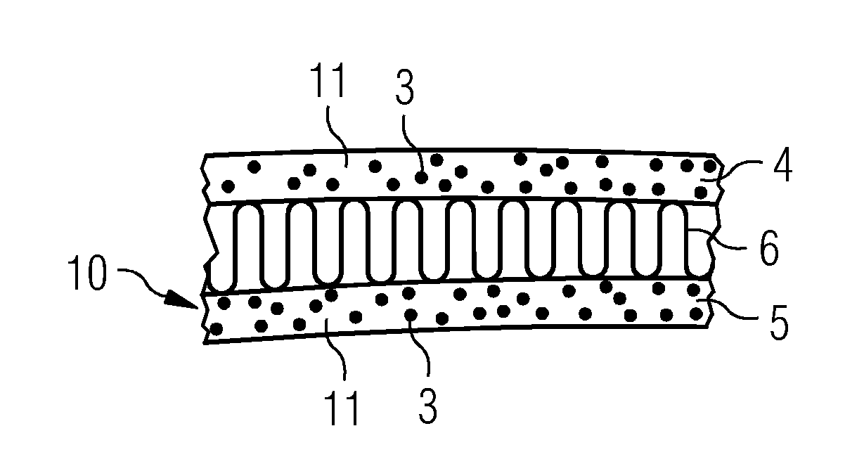
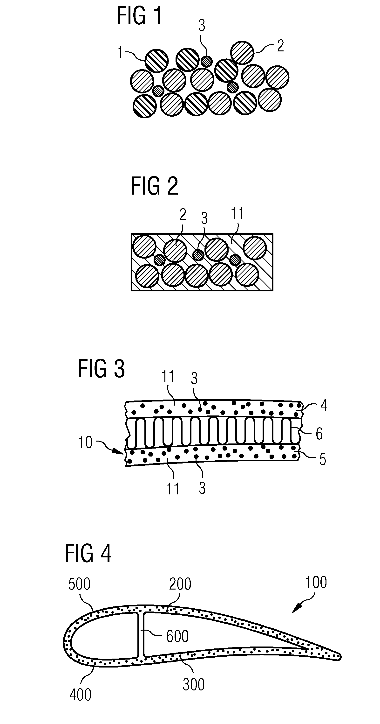
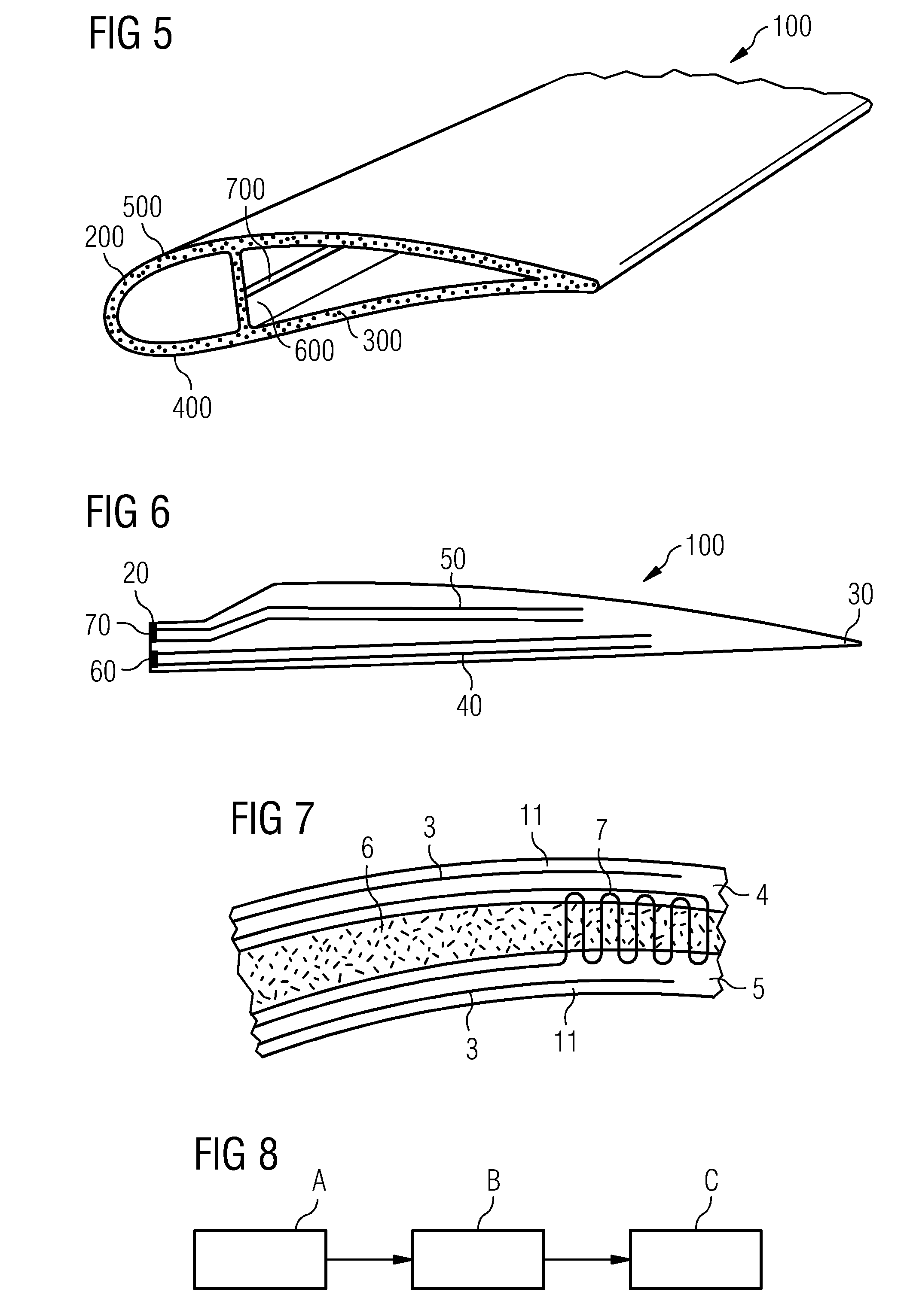
[0063]FIG. 1 shows a schematic view of a laminate part of an embodiment of the sandwich laminate before heating. A mixture of thermoplastic fibres 1, reinforcing fibres 2, and electrically conductive fibres 3 are shown in its cross section. The electrically conductive fibres are appropriately placed so that they are sufficiently surrounded by the thermoplastic fibres 1 and reinforcing fibres 2 to avoid any short circuits between conductive fibres 3.

[0064]FIG. 2 shows the same laminate part of FIG. 1 after heating, i.e. after current was led through the electrically conductive fibres 3 and thereby heated them to a temperature higher than the melting point of the thermoplastic fibre material 1. After the thermoplastic fibres 1 have been melted and consolidated by cooling, the electrically conductive fibres 3 and the reinforcing fibres 2 are appropriately distributed in a rigid thermoplastic matrix material 11. Due to the accurate placement of the electrically conductive fibres 3 in th...


PUM

PropertyMeasurementUnit
Temperatureaaaaaaaaaa
Electrical conductivityaaaaaaaaaa
Melting pointaaaaaaaaaa

Abstract

A sandwich laminate for wind turbine blades includes a sandwich core material and an upper laminate part and a lower laminate part, wherein the upper laminate part and the lower laminate part have a thermoplastic matrix material and heating elements. The heating elements are electrically conductive fibres constituting electric circuits in the interior part of the thermoplastic matrix. Further, a wind turbine blade including such a sandwich laminate as well as a method of manufacturing such a sandwich laminate are provided.

Description

CROSS REFERENCE TO RELATED APPLICATIONS[0001]This application claims priority of European Patent Application No. 11195242.0 EP filed Dec. 22, 2011. All of the applications are incorporated by reference herein in their entirety.FIELD OF INVENTION[0002]A sandwich laminate, in particular for wind turbine blades, comprises a sandwich core material and an upper laminate part and a lower laminate part, wherein the upper laminate part and the lower laminate part comprise a thermoplastic matrix material and heating elements. Further, a wind turbine blade with such a sandwich laminate and a method of manufacturing a sandwich laminate are provided. Furthermore, a finishing method and a de-icing method of a wind turbine blade are provided.BACKGROUND OF INVENTION[0003]Wind turbine blades for rotors of wind turbines have a length of about 40 meters or more, sometimes about 90 or 100 meters. The wind turbine blades need to be very stiff and, thus, usually constitute a shell structure comprising a...

Claims


Application Information

Patent Timeline
27 Jun 2013
Publication
US20130164133A1
IPC
F03D11/00; H05B3/18
CPC
F03D11/0025; B32B27/00; B32B5/08; H05B3/18; F03D1/0675; F03D80/40; Y02E10/74; Y02E10/72
Inventors
GROVE-NIELSEN, ERIK