Centrifugal fan

a centrifugal fan and fan body technology, applied in the direction of positive displacement liquid engine, piston pump, liquid fuel engine, etc., can solve the problems of increasing the wind noise of the centrifugal fan and the difficulty of reducing so as to reduce the axial dimension of the centrifugal fan and reduce the effect of wind nois

Inactive Publication Date: 2013-06-27
NIPPON DENSAN CORP
View PDF12 Cites 28 Cited by
  • Summary
  • Abstract
  • Description
  • Claims
  • Application Information

AI Technical Summary

Benefits of technology

[0009]According to the above preferred embodiment of the present invention, the electronic component arranging portion is arranged radially outward of the impeller. Therefore, the electronic component arranging portion does not overlap with the motor or the impeller in an axial direction. This makes it possible to reduce the axial dimension of the centrifugal fan. In addition, the electronic component arranging portion is arranged in an area where a wind channel has a large width. This contributes to reducing wind noise caused by the electronic component arranging portion.

Problems solved by technology

However, when the electronic components on the circuit board are arranged to overlap with the motor or the impeller in an axial direction, it is difficult to achieve a reduction in the axial dimension of the centrifugal fan.
However, when the circuit board, or a portion thereof, is arranged in the wind channel, wind impinges on the circuit board, and this may cause an increase in wind noise of the centrifugal fan.

Method used


Image

  • Centrifugal fan
  • Centrifugal fan
  • Centrifugal fan

Examples


Embodiment Construction

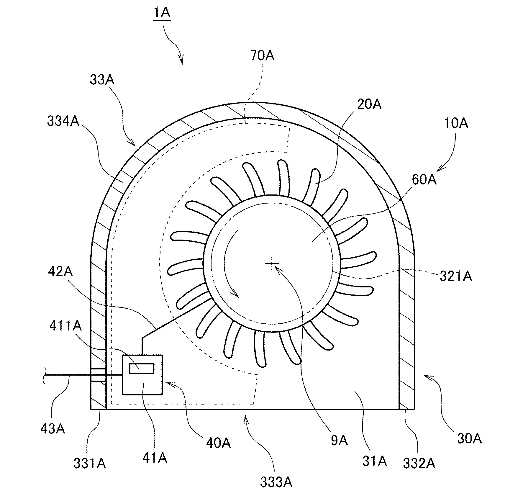
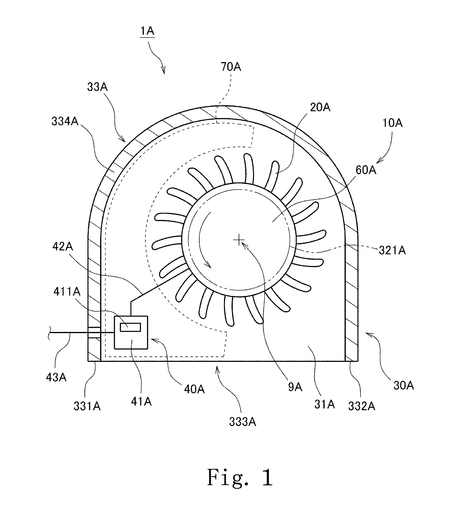
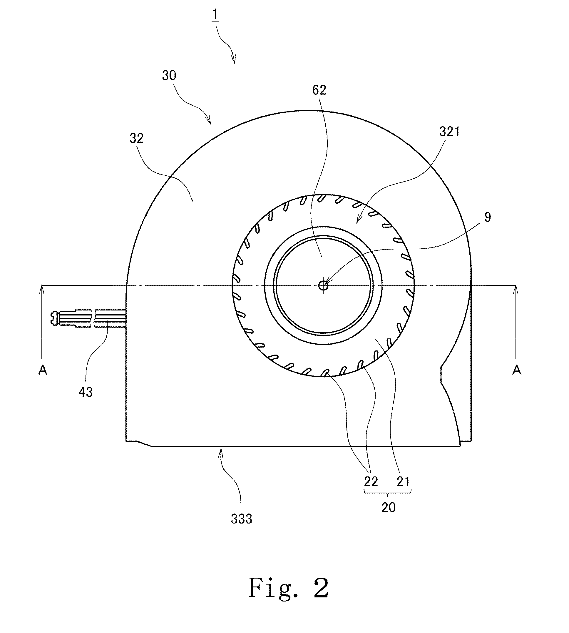
[0021]Hereinafter, preferred embodiments of the present invention will be described with reference to the accompanying drawings. It is assumed herein that a direction parallel to a central axis of a motor is referred to by the term “axial direction”, “axial”, or “axially”, that directions perpendicular to the central axis of the motor are referred to by the term “radial direction”, “radial”, or “radially”, and that a circumferential direction about the central axis of the motor is referred to by the term “circumferential direction”, “circumferential”, or “circumferentially”. It is also assumed herein that a vertical direction is the axial direction, and that a side on which a top plate of a housing is arranged with respect to a bottom plate of the housing is defined as an upper side. The shape of each member or portion and relative positions of different members or portions will be described based on the above assumptions. It should be noted, however, that the above definitions of t...


PUM


Abstract

A side wall of a centrifugal fan includes a gap expanding portion arranged to gradually expand a gap between an impeller and the side wall from an upstream end toward a downstream end with respect to a rotation direction of a rotating portion. In the centrifugal fan, an electronic component arranging portion of a board is arranged in an area surrounded by the gap expanding portion, the impeller, and an air outlet, and accordingly does not overlap with a motor or the impeller in an axial direction. The electronic component arranging portion is arranged in an area extending, in a circumferential direction about a central axis, from a position 180 degrees upstream from a middle of the air outlet downstream to the middle of the air outlet, that is, in an area where a wind channel has a large width.

Description

BACKGROUND OF THE INVENTION[0001]1. Field of the Invention[0002]The present invention relates to a centrifugal fan.[0003]2. Description of the Related Art[0004]Centrifugal fans used for internal cooling have often been installed in electronic devices, such as personal computers. Once such a centrifugal fan is driven, an air current is produced inside a case of the electronic device. This leads to a reduction in accumulation of heat inside the case. The structure of such a known centrifugal fan is described, for example, in JP-A 2001-135964.[0005]Centrifugal fans include circuit boards arranged to supply drive currents to windings. Also, in many known centrifugal fans, a magnetic sensor arranged to detect the rotation rate of an impeller is mounted on the circuit board. Thus, in many known centrifugal fans, a circuit board having a variety of electronic components mounted thereon is disposed in the vicinity of a rotating portion of a motor or the impeller.[0006]However, when the elec...

Claims


Application Information

Patent Timeline
Patent Type & Authority Applications(United States)
IPC IPC(8): F04B35/04
CPCF04D17/16F04D29/5813F04D25/08F04D25/0633H02K7/14H02K9/06H02K21/22
Inventor MATSUBA, NAOKITESHIMA, HIROYOSHIIDA, KIYOTO
Owner NIPPON DENSAN CORP
Why Eureka
Try Eureka