Connector with integrated heat sink

a technology of heat sink and connector, which is applied in the direction of conduction heat transfer modification, coupling device connection, instruments, etc., can solve the problems of physical limitation of the medium used to transmit signals from between the plug connector and the connector, and the difficulty of overcoming them

Active Publication Date: 2013-06-27
MOLEX INC
View PDF13 Cites 49 Cited by
  • Summary
  • Abstract
  • Description
  • Claims
  • Application Information

AI Technical Summary

Problems solved by technology

As data rates have increased, one issue that has been difficult to overcome is the physical limitation of medium that is used to transmit signals from between the plug connectors.
Passive cables, for example, are cost effective for shorter distances but tend to be limited with respect to distance as signal frequencies increase.
Active copper and fiber optic cables are well suited to transmit signals over longer distances but require power and thus tend to create thermal issues if the connector system is not properly designed.
One solution has been to use a riding heat sink on the receptacle but the existing solutions, while somewhat effective, have trouble providing sufficient thermal handling capacity.

Method used


Image

  • Connector with integrated heat sink
  • Connector with integrated heat sink
  • Connector with integrated heat sink

Examples


Embodiment Construction

[0019]The detailed description that follows describes exemplary embodiments and is not intended to be limited to the expressly disclosed combination(s). Therefore, unless otherwise noted, features disclosed herein may be combined together to form additional combinations that were not otherwise shown for purposes of brevity.

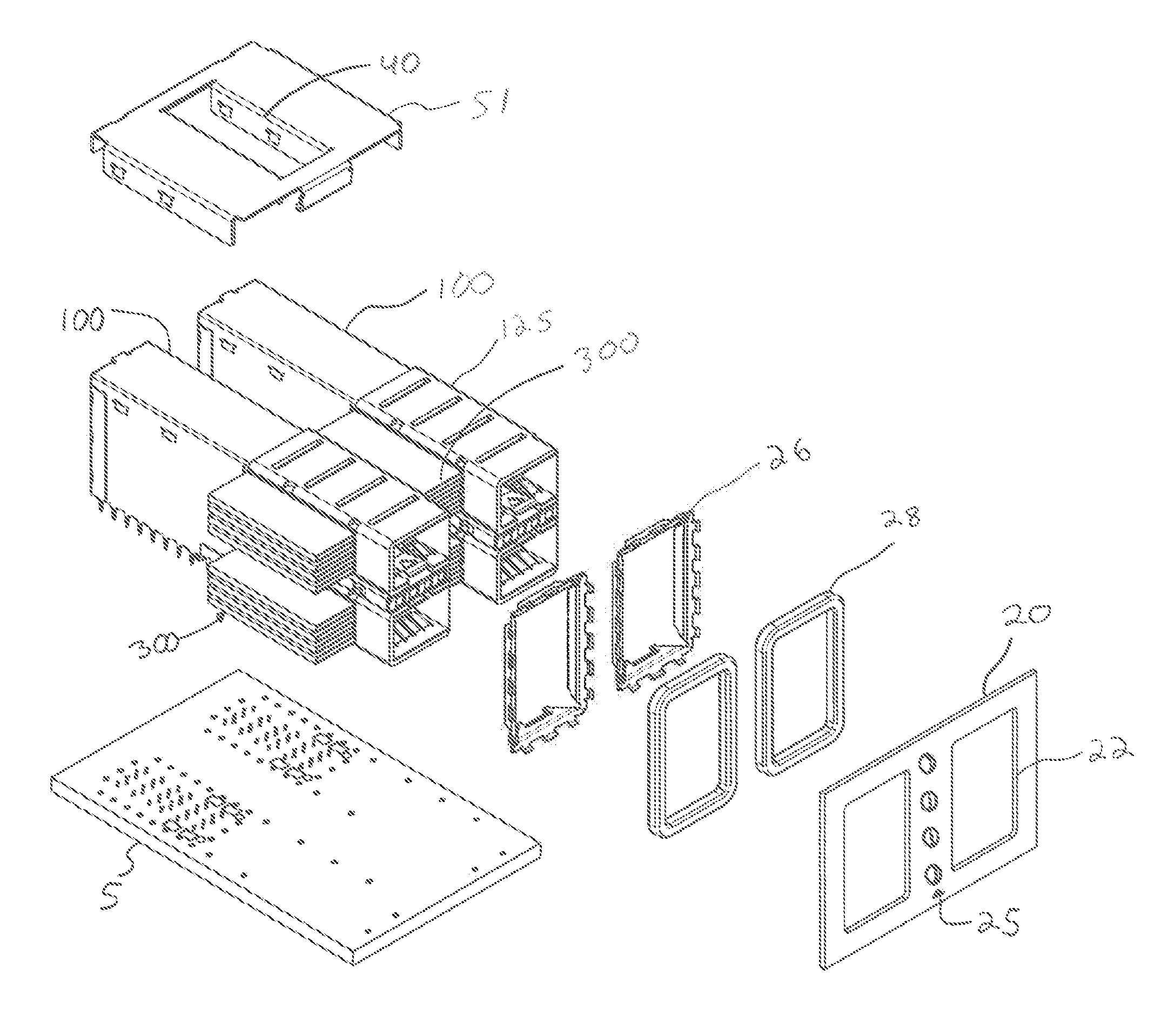
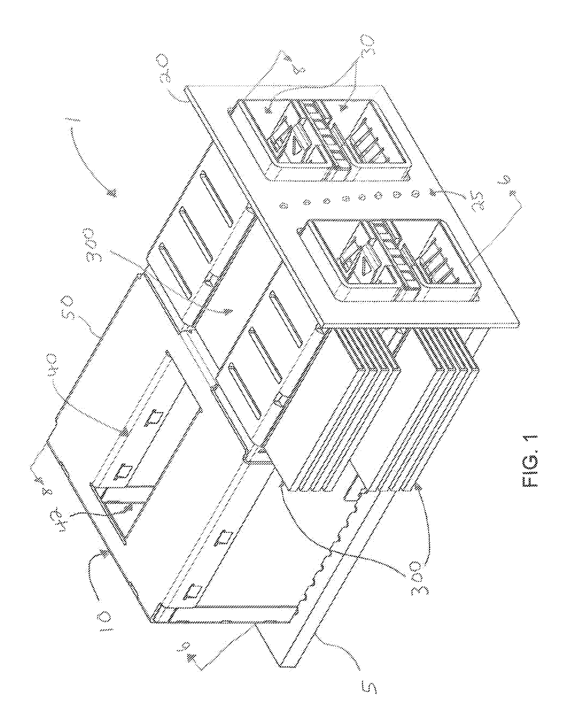
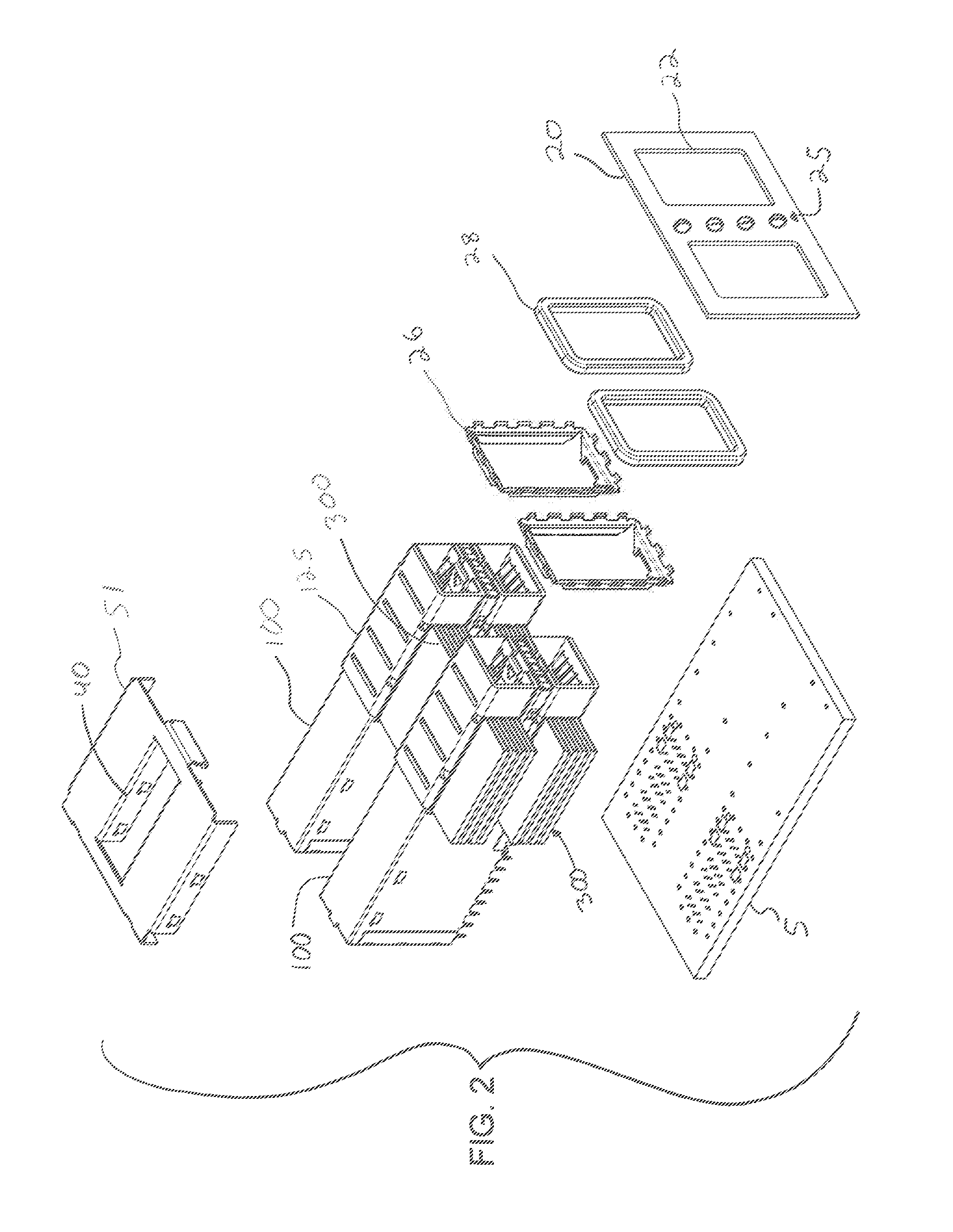
[0020]As can be appreciated from the figures, a receptacle connector 10 is typically mounted behind a bezel 20 (of which a partial bezel 20 is depicted). If the bezel is considered positioned at a front of the receptacle and the opposite end is considered a rear, then a system architecture may allow for air flow from front to rear. If the system architecture is set up to allow for air flow from front to rear then the bezel 20 can include air intake 25, which can be formed from one or more desirably shaped apertures in the bezel. As can be appreciated, the size of the apertures, as well as the pattern of such apertures, is primarily dictated by the desired air flow...


PUM


Abstract

A receptacle connector defines a port. The port is provided with spring fingers that are configured to engage a mating module. The spring fingers are thermally coupled to a heat transfer plate that can be configured to provide part of a cage that defines the port. Fins can be mounted on or integrated into the heat transfer plate. In operation, thermal energy from an inserted module is transferred from the module to spring fingers and then to the heat transfer plate and then to a thermal dissipation system.

Description

RELATED APPLICATIONS[0001]This application claims priority to U.S. Provisional Application No. 61 / 556,890, filed Nov. 8, 2011 and to U.S. Provisional Application No. 61 / 640,786, filed May 1, 2012, both of which are incorporated herein by reference in their entirety.BACKGROUND OF THE INVENTION[0002]1. Field of the Invention[0003]The present invention relates to field of electrical connectors, more specifically to the field of input / output (I / O) connectors.[0004]2. Description of Related Art[0005]Typical I / O connector systems include a cable assembly and a board mounted connector. The cable assembly, which commonly includes a pair of plug connectors on opposite ends of a cable, is configured to transmit signals over a desired distance. The board mounted connector, which is typically a receptacle positioned in a panel with the receptacle configured to receive and mate with the plug connector.[0006]As data rates have increased, one issue that has been difficult to overcome is the physic...

Claims


Application Information

Patent Timeline
Patent Type & Authority Applications(United States)
IPC IPC(8): H01R13/533F28F3/02
CPCH05K7/20509G02B6/4201F28F3/02H01R13/533
Inventor REGNIER, KENT E.LONG, JERRY A.
Owner MOLEX INC
Why Eureka
Try Eureka