
Fuel nozzles for injecting fuel in a gas turbine combustor

a technology of fuel nozzles and gas turbines, which is applied in the direction of machines/engines, mechanical equipment, lighting and heating apparatus, etc., can solve the problems of liquid fuel clogging of mixing tubes, fuel nozzles that are not designed to direct liquid fuel through mixing tubes,

Active Publication Date: 2013-07-04
GENERAL ELECTRIC CO
View PDF18 Cites 27 Cited by
  • Summary
  • Abstract
  • Description
  • Claims
  • Application Information

AI Technical Summary

Benefits of technology

The patent describes different embodiments of a gas turbine fuel nozzle system. These embodiments include a gas turbine fuel nozzle with a fuel plenum plate and a liquid fuel cartridge, as well as a system with multiple sector nozzles and a liquid fuel cartridge. The nozzle system also includes a plurality of mixing tubes that produce a fuel-air mixture and direct it towards a combustion region. The technical effects of the patent are improved fuel mixing and more precise control of fuel injection, which can result in improved combustion efficiency and reduced emissions.

Problems solved by technology

However, the fuel nozzles may not be designed to direct liquid fuel through the mixing tubes.
For example, the mixing tubes may become clogged by liquid fuel due to the small size of the mixing tubes.

Method used


Image

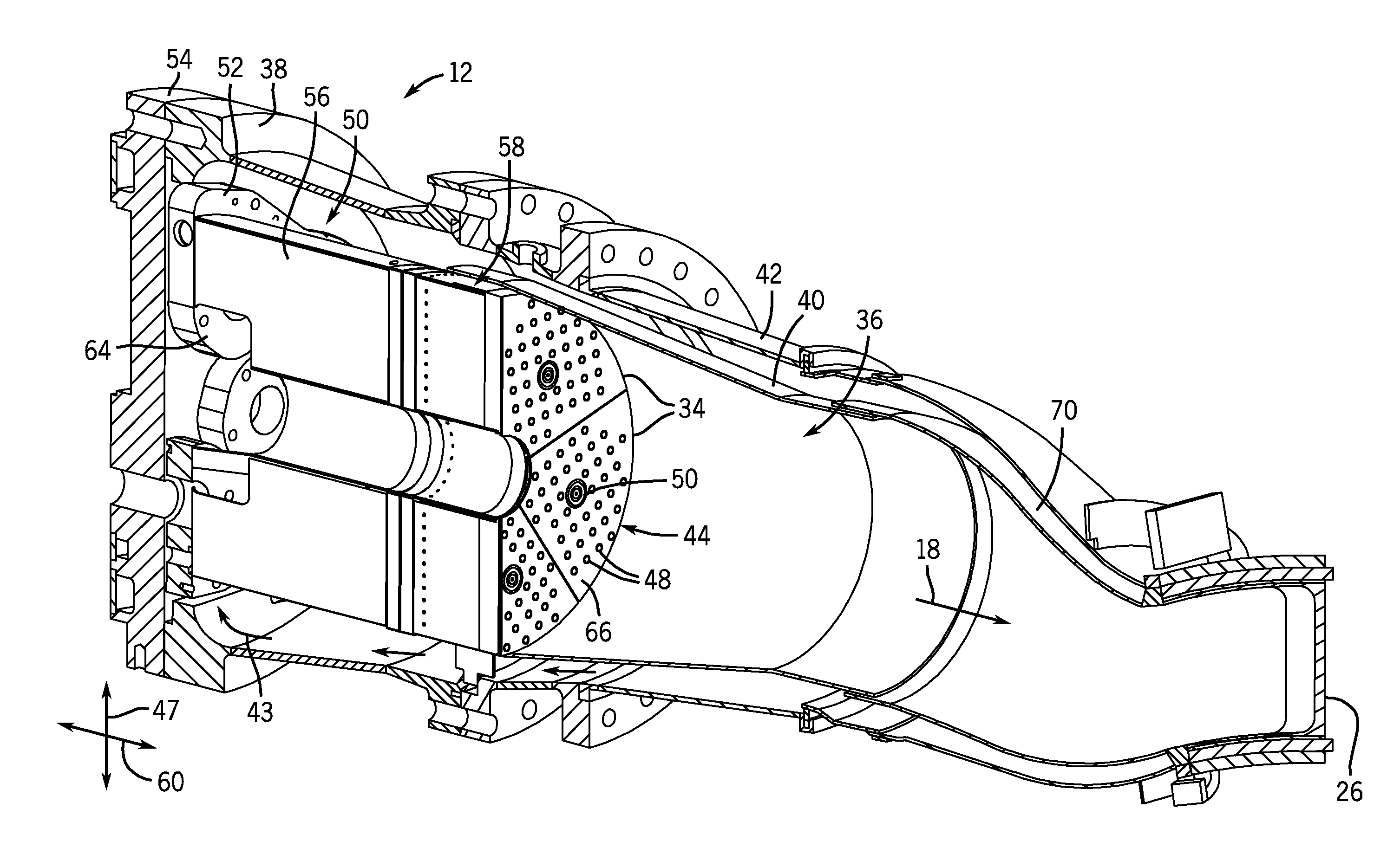
  • Fuel nozzles for injecting fuel in a gas turbine combustor
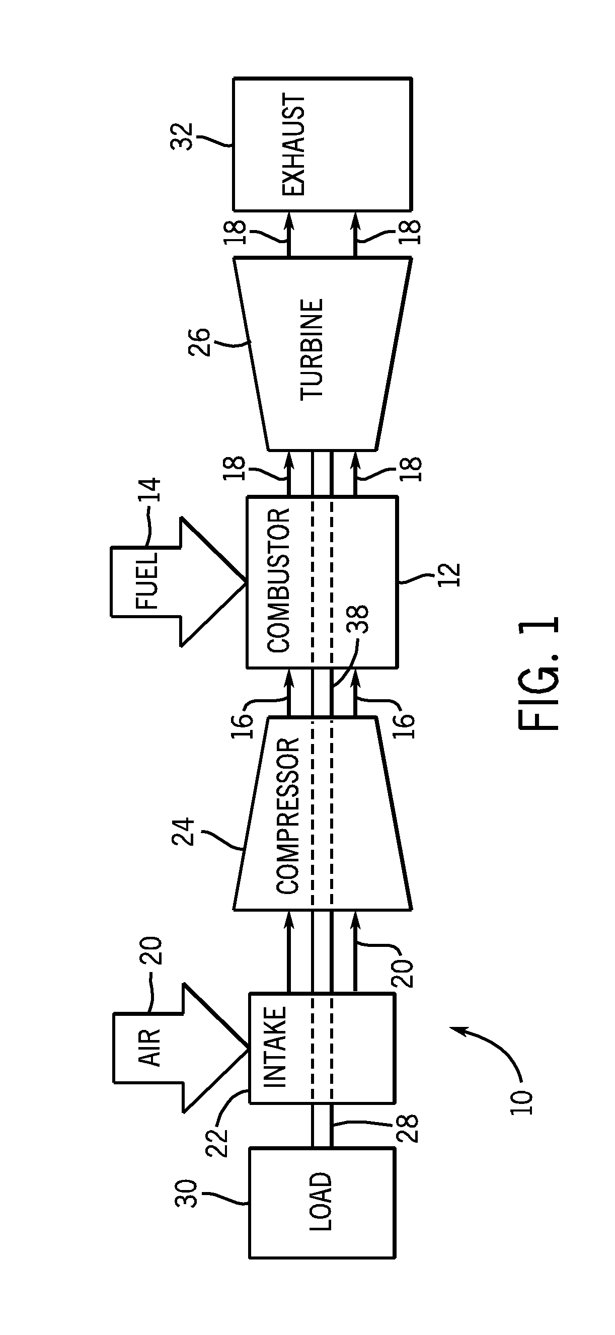
  • Fuel nozzles for injecting fuel in a gas turbine combustor
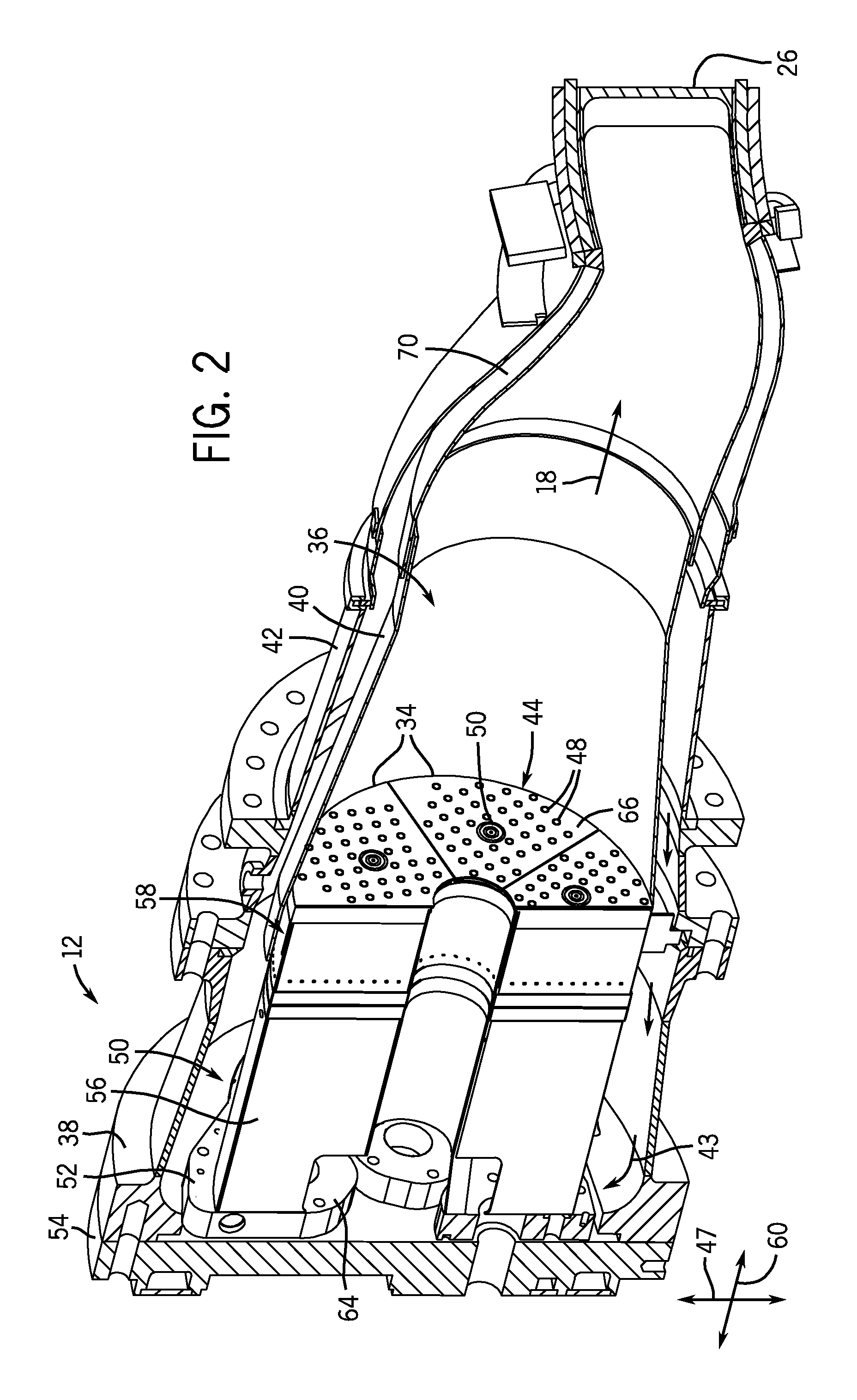
  • Fuel nozzles for injecting fuel in a gas turbine combustor

Examples


Embodiment Construction

[0016]One or more specific embodiments of the present invention will be described below. In an effort to provide a concise description of these embodiments, all features of an actual implementation may not be described in the specification. It should be appreciated that in the development of any such actual implementation, as in any engineering or design project, numerous implementation-specific decisions must be made to achieve the developers' specific goals, such as compliance with system-related and business-related constraints, which may vary from one implementation to another. Moreover, it should be appreciated that such a development effort might be complex and time consuming, but would nevertheless be a routine undertaking of design, fabrication, and manufacture for those of ordinary skill having the benefit of this disclosure.

[0017]When introducing elements of various embodiments of the present invention, the articles “a,”“an,”“the,” and “said” are intended to mean that ther...


PUM


Abstract

Fuel nozzles for gas turbines are provided that include liquid fuel cartridges. In one embodiment, a fuel nozzle includes a fuel plenum plate separating an air plenum from a fuel plenum. The fuel nozzle also includes a plurality of mixing tubes extending through the fuel plenum from the fuel plenum plate to a face plate. Each mixing tube includes an air inlet configured to receive air from the air plenum, a fuel inlet disposed in a tube wall within the fuel plenum to direct fuel from the fuel plenum into the mixing tube to produce a fuel-air mixture, and a fuel-air outlet configured to discharge the fuel-air mixture away from the face plate into a combustion region. The fuel nozzle further includes a liquid fuel cartridge extending through the air plenum and the fuel plenum to the face plate. The liquid fuel cartridge includes a liquid fuel passage.

Description

BACKGROUND OF THE INVENTION[0001]The subject matter disclosed herein relates to fuel nozzles and more specifically, to fuel nozzles for gas turbine combustors.[0002]In general, gas turbines combust a mixture of compressed air and fuel within a combustor to produce hot combustion gases. The hot combustion gases rotate blades of the turbine to rotate a shaft that drives a load, such as an electrical generator. Fuel nozzles within the combustor inject fuel and air into the combustor. In some designs, the fuel nozzles include one or more mixing tubes that pre-mix the fuel and air before the fuel and air enters the combustion zone. For example, the mixing tubes may be employed to mix a gaseous fuel with air. However, the fuel nozzles may not be designed to direct liquid fuel through the mixing tubes. For example, the mixing tubes may become clogged by liquid fuel due to the small size of the mixing tubes.BRIEF DESCRIPTION OF THE INVENTION[0003]Certain embodiments commensurate in scope wi...

Claims


Application Information

Patent Timeline
Patent Type & Authority Applications(United States)
IPC IPC(8): F23R3/28
CPCF23R3/286Y02E20/16F23D2900/00008
Inventor BERRY, JONATHAN DWIGHT
Owner GENERAL ELECTRIC CO
Learn More