Eureka AIR delivers breakthrough ideas for toughest innovation challenges, trusted by R&D personnel around the world.

Thermal module

Inactive Publication Date: 2013-07-04
ASIA VITAL COMPONENTS SHENZHEN CO LTD
View PDF1 Cites 4 Cited by
  • Summary
  • Abstract
  • Description
  • Claims
  • Application Information

AI Technical Summary

Benefits of technology

The present invention provides a thermal module with better heat transfer efficiency. The heat pipe is fully utilized to conduct heat, resulting in enhanced heat dissipation efficiency. Additionally, the thermal module overcomes the issue of shortcomings in conventional thermal modules where the ends of the heat pipe fail to conduct heat as invalid ends, leading to decreased heat transfer efficiency.

Problems solved by technology

Otherwise, the temperature will rise to cause unstable operation.
This will greatly deteriorate the heat dissipation performance of the heat sink 3.
Such structure also has the above problem that the two ends of the heat pipe 5 often fail to conduct the heat as invalid ends to make the heat pipe 5 lose its heat transfer function.
Therefore, the heat sink 3 with the heat pipes 5 still can hardly achieve an expected effect and the heat transfer performance of the heat sink 3 with the heat pipes 5 is still limited.

Method used


Image

  • Thermal module
  • Thermal module
  • Thermal module

Examples


Embodiment Construction

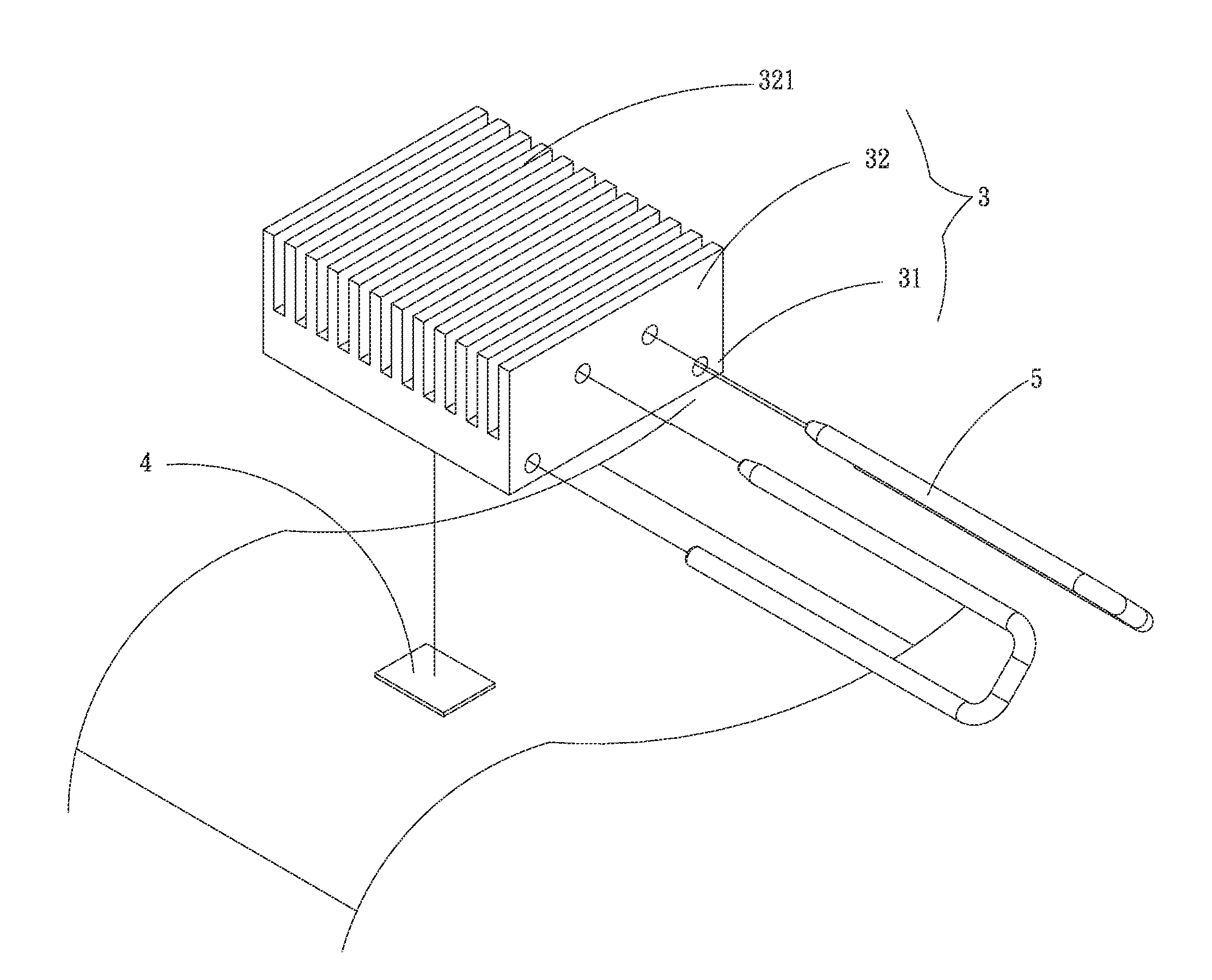
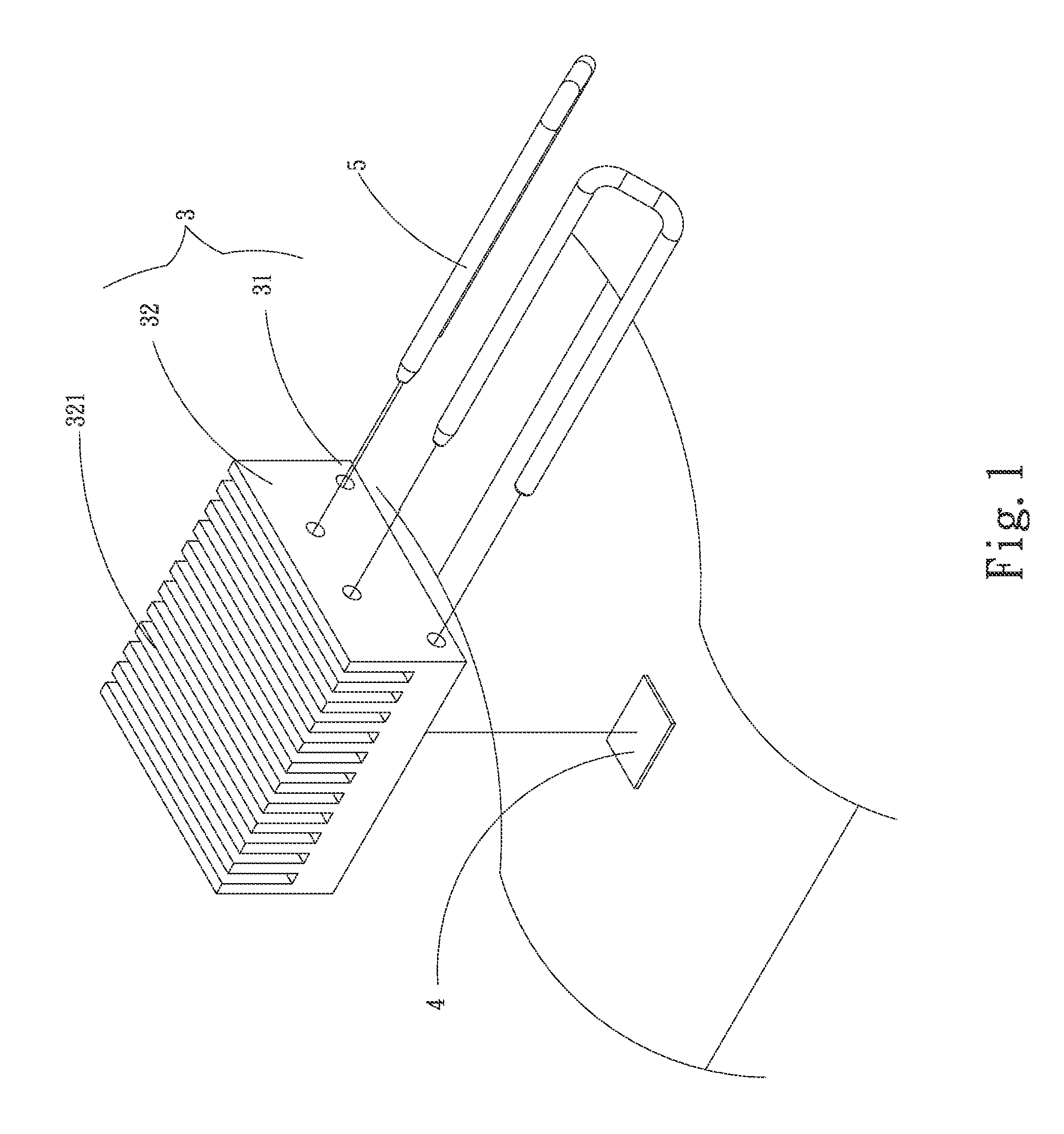
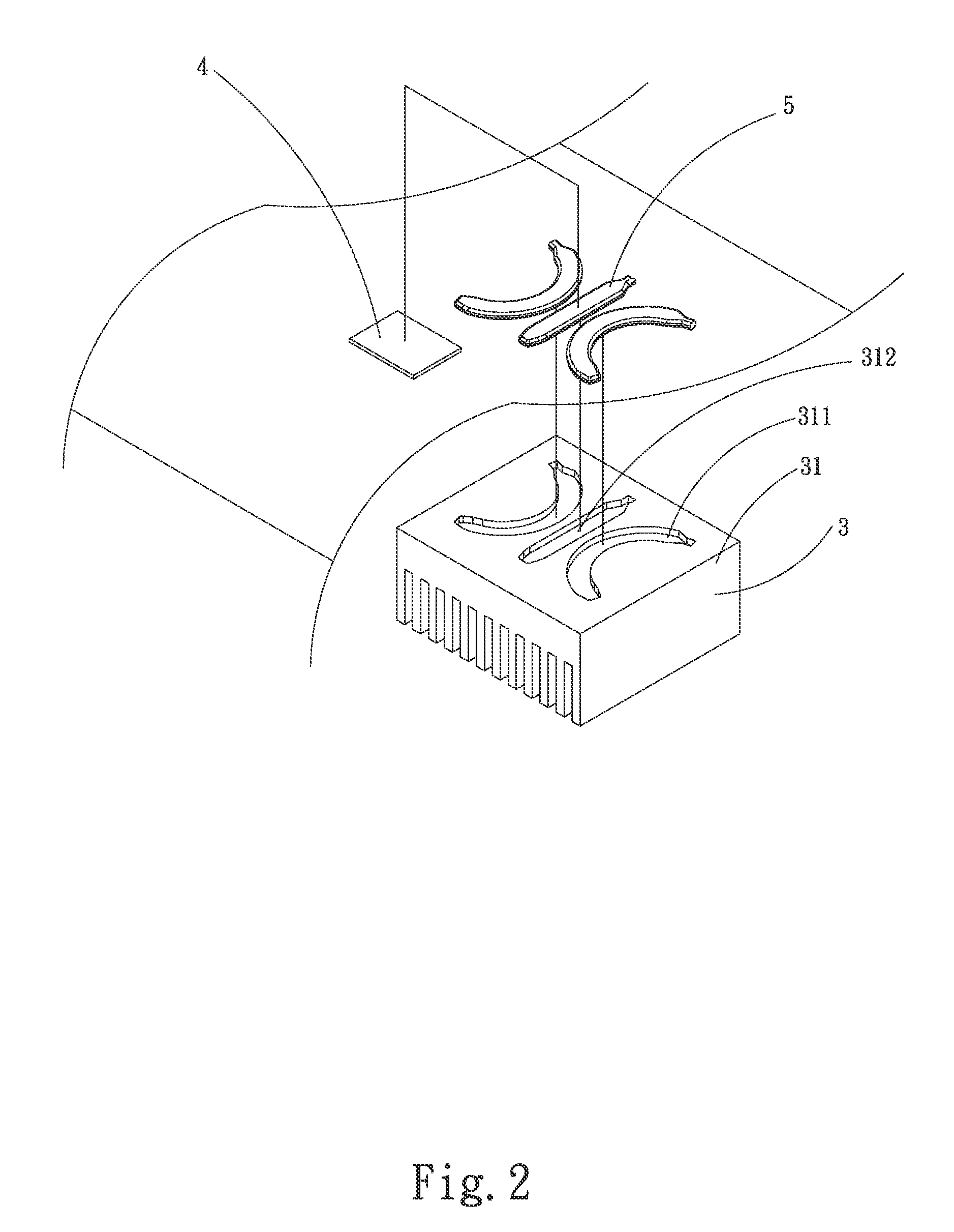
[0029]Please refer to FIGS. 3, 4 and 5. FIG. 3 is a perspective exploded view of a first embodiment of the thermal module of the present invention. FIG. 4 is a perspective assembled view of the first embodiment of the thermal module of the present invention. FIG. 5 is a sectional assembled view of the first embodiment of the thermal module of the present invention. According to the first embodiment, the thermal module 1 includes a heat sink 11 and a heat pipe 12.

[0030]The heat sink 11 has a heat absorption section 111 and a heat dissipation section 112. The heat dissipation section 112 has multiple radiating fins 1121. The heat absorption section 111 is formed with at least one receiving groove 113.

[0031]The heat pipe 12 is received in the receiving groove 113. The heat pipe 12 has a first end 121, a second end 122, a middle section 123 and at least one conduction section 124. The first and second ends 121, 122 and the middle section 123 are arranged in adjacency to each other to to...


PUM


Abstract

A thermal module includes a heat sink and a heat pipe. The heat sink has a heat absorption section and a heat dissipation section. The heat dissipation section has multiple radiating fins. The heat absorption section is formed with at least one receiving groove. The heat pipe is received in the receiving groove. The heat pipe has a first end, a second end, a middle section and at least one conduction section. The first and second ends and the middle section are arranged in adjacency to each other to together define a first section. The conduction section winds around the first section.

Description

[0001]This application claims the priority benefit of Taiwan patent application number 100149731 filed on Dec. 30, 2011.BACKGROUND OF THE INVENTION[0002]1. Field of the Invention[0003]The present invention relates generally to a thermal module, and more particularly to a thermal module, which has better heat transfer efficiency and overcomes the shortcoming of the conventional thermal module that the ends of the heat pipe fail to conduct heat as invalid ends.[0004]2. Description of the Related Art[0005]Following the advance of semiconductor technique, the volume of integrated circuit has been more and more minified. With respect to an internal processor or the like integrated circuit electronic component, the faster the operation speed is, the more the heat generated per unit time is. The heat must be dissipated in time. Otherwise, the temperature will rise to cause unstable operation. In general, a heat sink is arranged on the internal processor to help in dissipating the heat so a...

Claims


Application Information

Patent Timeline
IPC IPC(8): F28D15/04
CPCF28D15/0233F28D15/0275H01L23/427H01L23/467H01L2924/0002H01L2924/00
Inventor WU, CHUN-MING
Owner ASIA VITAL COMPONENTS SHENZHEN CO LTD
Why Eureka
Eureka Blog
Learn More