Duty cycle controlling circuit, duty cycle adjusting cell, and dutycycle detecting circuit

a technology of controlling circuit and detecting circuit, which is applied in the direction of pulse generator, pulse manipulation, pulse technique, etc., can solve the problems of dcd (duty cycle distortion) accuracy over pvt issues, circuits may have high power consumption, and circuits may have large pss (power supply sensitivity), so as to achieve low power saving magnitude, wide range, and high accuracy

Active Publication Date: 2013-07-04
NAN YA TECH
View PDF2 Cites 16 Cited by
  • Summary
  • Abstract
  • Description
  • Claims
  • Application Information

AI Technical Summary

Benefits of technology

[0005]One objective of the present invention is to provide a duty cycle controlling circuit having smaller circuit region, precise duty cycle controlling and fast locking time.
[0009]In view of above-mentioned embodiments, the duty cycle controlling circuit according to the present invention may have the advantage of: wide range duty cycle correction below 10% to beyond 90%, forward path delay reduction, ultra low power saving magnitude, higher accuracy, fast initialization, and smaller circuit region.

Problems solved by technology

However, traditional DCC circuits always include some defects.
For example, such circuits may have high power consumption, large PSS (power supply sensitivity), DCD (Duty Cycle Distortion) accuracy over PVT issues and longer clock forward path delay.
Besides, such circuits have large circuit region, slower locking time and slow duty cycle calculation response / tracking time.
Also, the accuracy for such circuits is limited by its duty adjuster inverter P / N ratio.

Method used


Image

  • Duty cycle controlling circuit, duty cycle adjusting cell, and dutycycle detecting circuit
  • Duty cycle controlling circuit, duty cycle adjusting cell, and dutycycle detecting circuit
  • Duty cycle controlling circuit, duty cycle adjusting cell, and dutycycle detecting circuit

Examples


Embodiment Construction

[0017]Certain terms are used throughout the description and following claims to refer to particular components. As one skilled in the art will appreciate, electronic equipment manufacturers may refer to a component by different names. This document does not intend to distinguish between components that differ in name but not function. In the following description and in the claims, the terms “include” and “comprise” are used in an open-ended fashion, and thus should be interpreted to mean “include, but not limited to . . . ”. Also, the term “couple” is intended to mean either an indirect or direct electrical connection. Accordingly, if one device is coupled to another device, that connection may be through a direct electrical connection, or through an indirect electrical connection via other devices and connections.

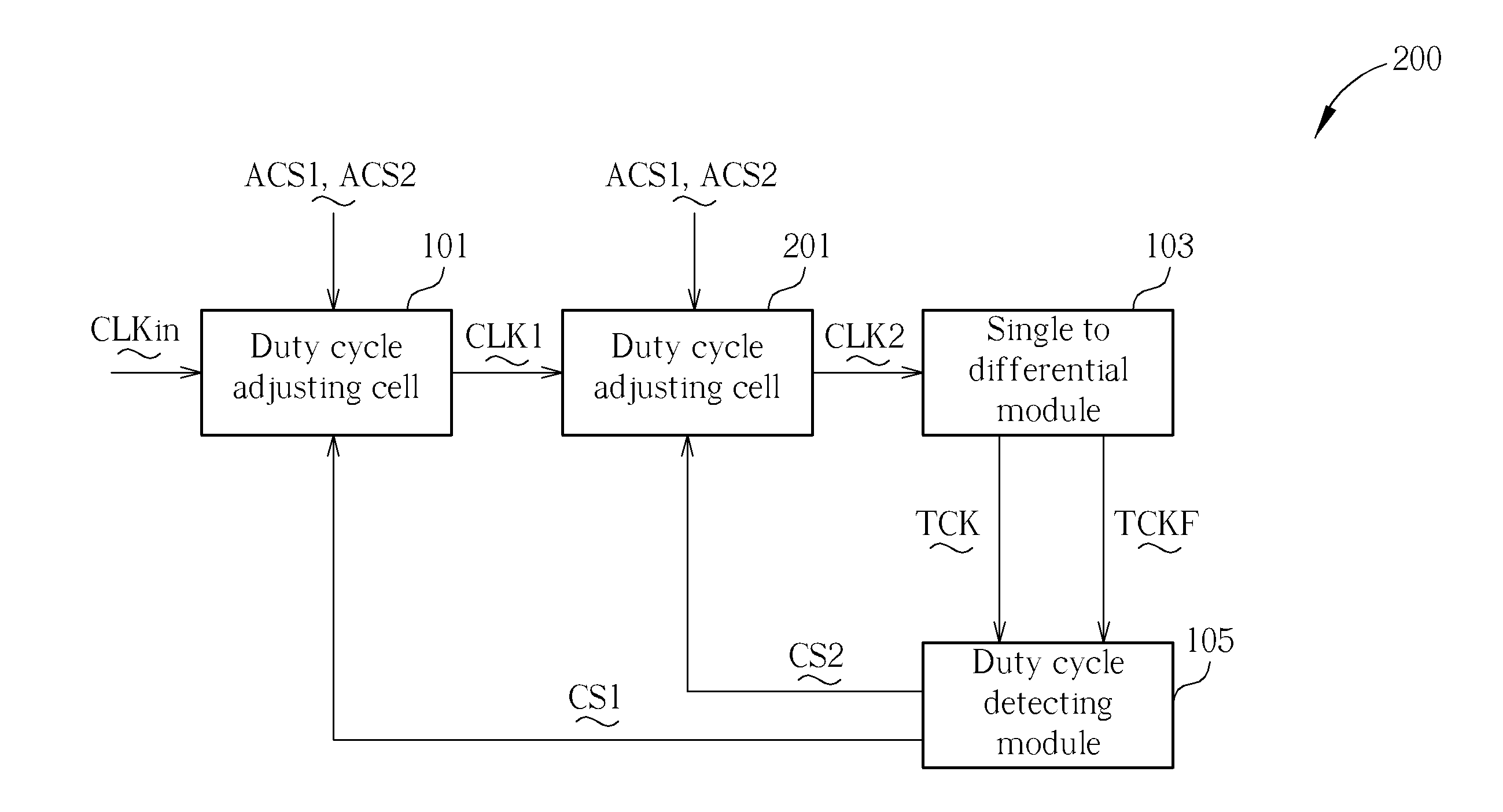
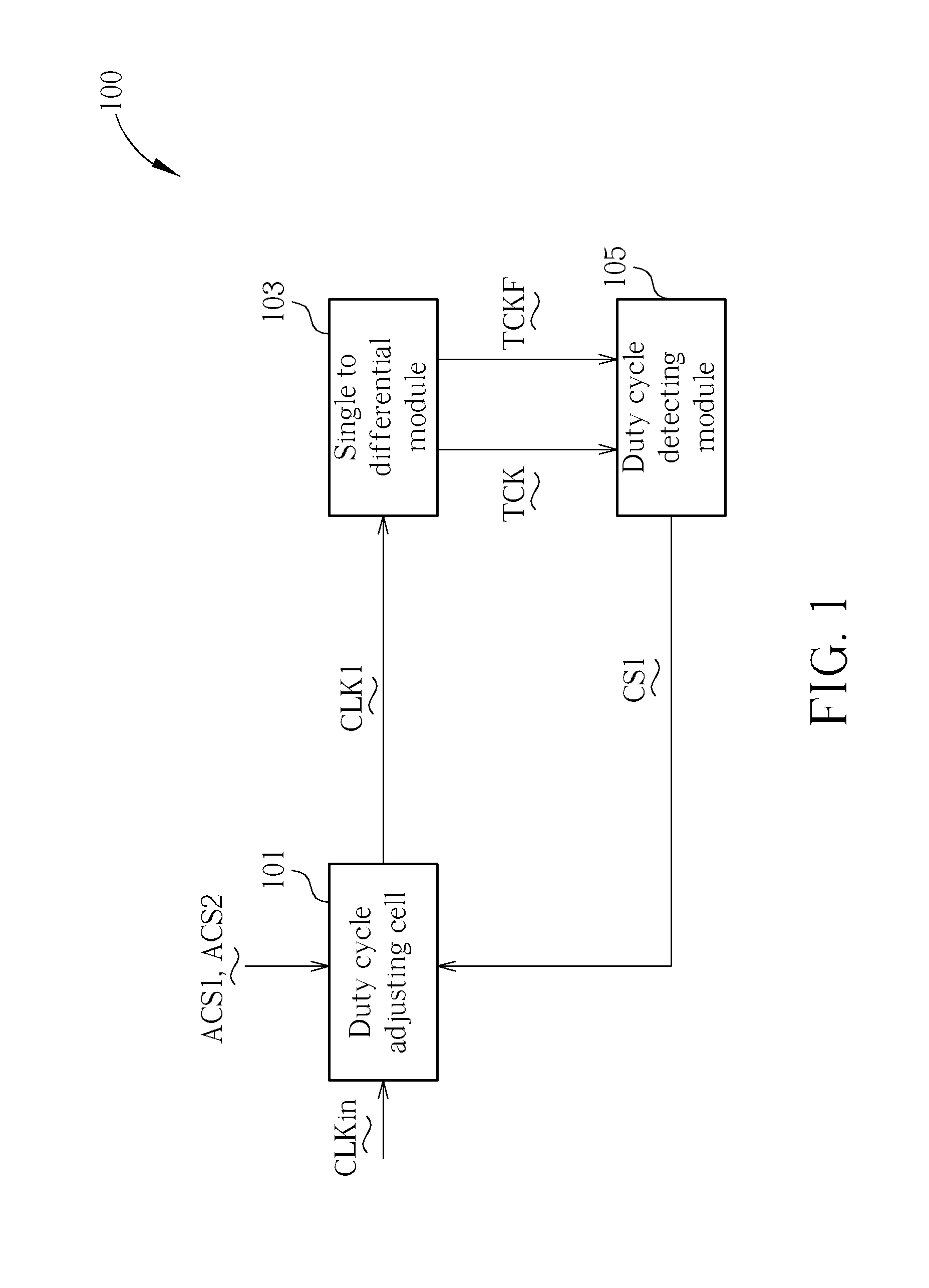
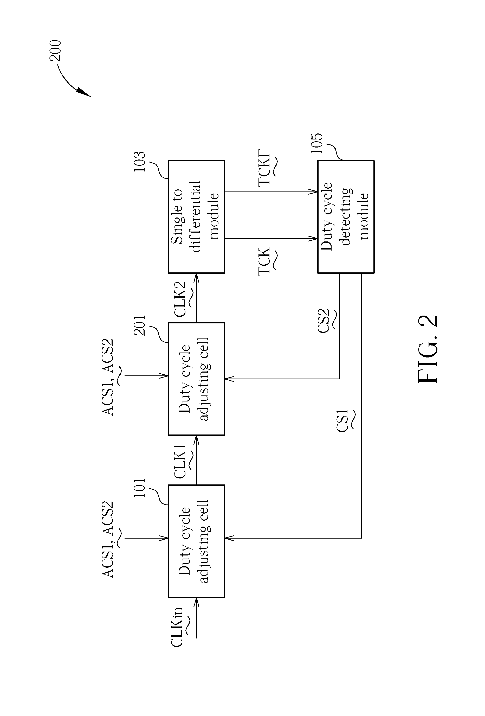
[0018]FIGS. 1 and 2 are block diagrams illustrating a duty cycle controlling circuit 100 according to different embodiments of the present invention. In this embodiment, ...


PUM


Abstract

A duty cycle controlling circuit for adjusting duty cycle of a target clock signal to a desired value, comprises: a first duty cycle adjusting cell, for receiving a first duty cycle control signal to adjust duty cycle of an input clock signal to generate a first output clock signal as the target clock signal; and a duty cycle detecting module, for generating the first duty cycle control signal according to the first output clock signal.

Description

BACKGROUND OF THE INVENTION[0001]1. Field of the Invention[0002]The present invention relates to a duty cycle controlling circuit, a duty cycle adjusting cell and a duty cycle detecting circuit, and particularly relates to a duty cycle controlling circuit that can utilize more than one a duty cycle adjusting cell to provide a clock signal with a precise duty cycle, a duty cycle adjusting cell and a duty cycle detecting circuit[0003]2. Description of the Prior Art[0004]Since the speed requirement of modern electronic device largely increases, DCC (duty cycle controlling) performance becomes more and more important. However, traditional DCC circuits always include some defects. For example, such circuits may have high power consumption, large PSS (power supply sensitivity), DCD (Duty Cycle Distortion) accuracy over PVT issues and longer clock forward path delay. Besides, such circuits have large circuit region, slower locking time and slow duty cycle calculation response / tracking time...

Claims


Application Information

Patent Timeline
Patent Type & Authority Applications(United States)
IPC IPC(8): H03K5/04
CPCH03K5/1565
Inventor MA, YANTAO
Owner NAN YA TECH
Why Eureka
Try Eureka