Frequency pattern detector

a detector and frequency technology, applied in the field of phaselocked loop (pll) circuitry, can solve the problems of limiting device performance, high cost of implementation, and time-consuming frequency band search across a band of several oscillators, and achieves efficient comparison of frequency, reduce convergence time for a pll, and fast lock time

Active Publication Date: 2011-06-07
MACOM CONNECTIVITY SOLUTIONS LLC
View PDF4 Cites 1 Cited by
  • Summary
  • Abstract
  • Description
  • Claims
  • Application Information

AI Technical Summary

Benefits of technology

[0010]Disclosed herein is a window sampling pattern means to efficiently compare the frequency between two clock signals. It enables a deterministic mechanism for phase-locked loop (PLL) convergence with a fast lock time. Unlike complex prior arts methods that require counters with many bits to accomplish frequency comparison, the simplest form of the system disclosed herein can be enabled with only 3 flip flops. The system also reduces the convergence time for a PLL, which is an extremely important requirement in many modern communication devices. The system takes advantage of cycle slipping between the two clocks, making the system 100 times faster than the conventional counter method when the signals being compared are close in frequency.

Problems solved by technology

This complex process limits device performance with regard to speed of acquisition, power consumption, and integrated circuit (IC) die area.
The mechanism, called frequency band search (FBS), must be simple, such that implementation is cost competitive.
A frequency band search across a band of several oscillators can be very time consuming, especially if the communication frequency is unknown.
However, this method requires a large number of clock cycles to make a comparison, especially if the two clocks are close in frequency.

Method used


Image

  • Frequency pattern detector
  • Frequency pattern detector
  • Frequency pattern detector

Examples


Embodiment Construction

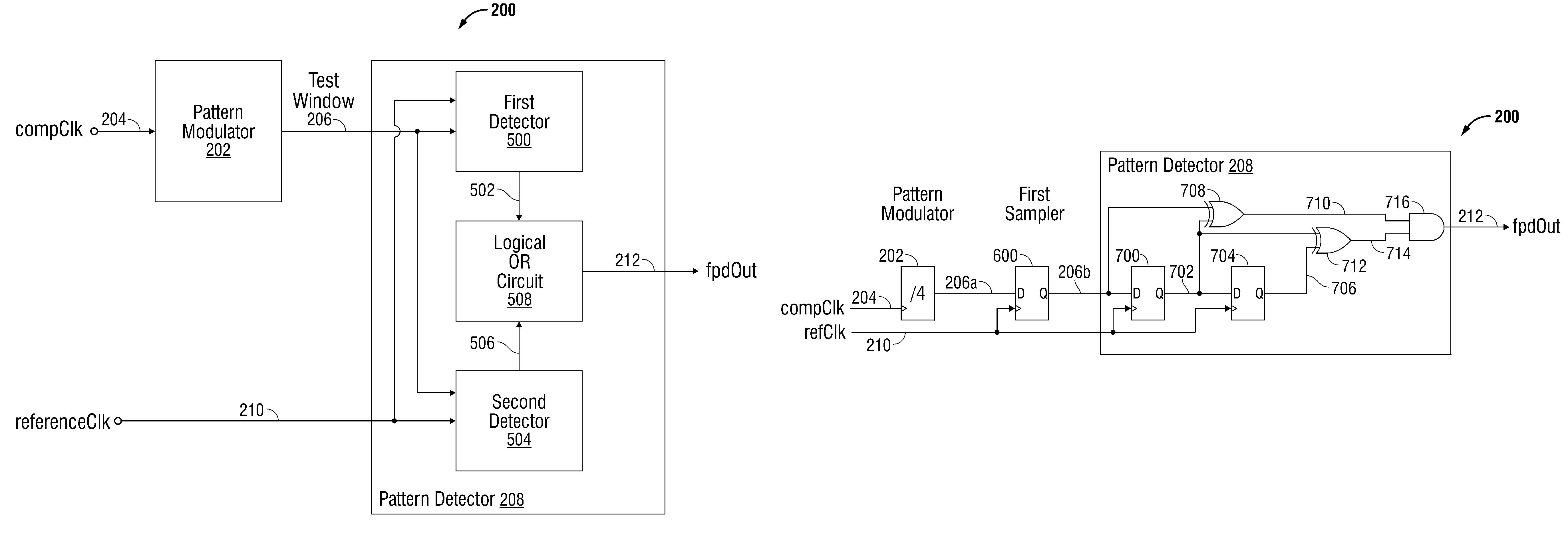
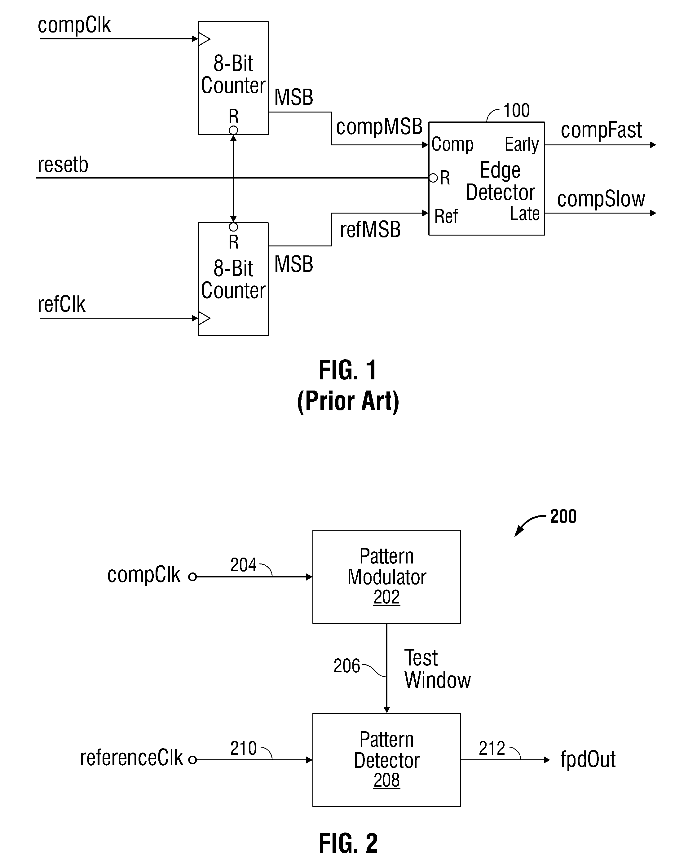
[0031]FIG. 2 is a schematic block diagram of a window sampling system for comparing a signal with an unknown frequency to a reference clock. The system 200 comprises a pattern modulator 202 having an input on line 204 to accept a compClk signal and an output on line 206 to supply a test window. The test window has a period equal to n compClk periods, where n is an integer greater than 1. A pattern detector 208 has an input on line 206 to accept the test window and an input on line 210 to accept a reference clock. The pattern detector 208 contrasts the test window with the reference clock. In response to failing to fit n reference clock periods inside the test window, the pattern detector 208 supplies a frequency pattern detector output signal (fpdOut) on line 212 indicating that the frequency of the compClk is greater than the reference clock frequency.

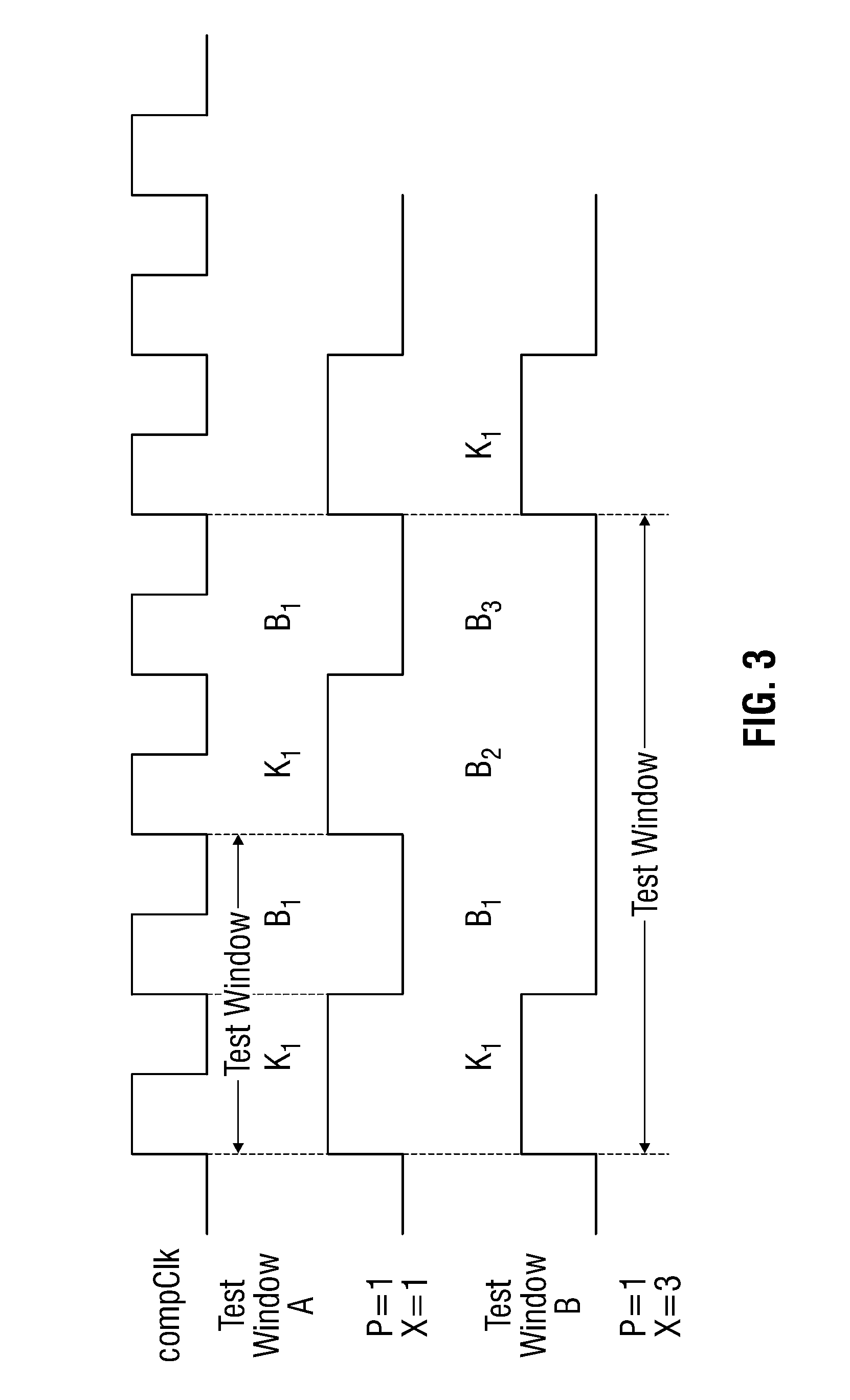
[0032]In one aspect, the pattern modulator 202 supplies a test window having a duty cycle with a first polarity (K) of p compClk per...


PUM


Abstract

A window sampling system and method are provided for comparing a signal with an unknown frequency to a reference clock. A pattern modulator accepts a compClk signal and supplies a test window with a period equal to n compClk periods, where n is an integer greater than 1. A pattern detector accepts the test window and a reference clock, and contrasts the test window with the reference clock. In response to failing to fit n reference clock periods inside the test window, the pattern detector supplies a frequency pattern detector output signal (fpdOut) indicating that the frequency of the compClk is greater than the reference clock frequency.

Description

BACKGROUND OF THE INVENTION[0001]1. Field of the Invention[0002]This invention generally relates to phase-locked loop (PLL) circuitry and, more particularly, to a system and method for simply determining the frequency of a signal with respect to a known reference frequency.[0003]2. Description of the Related Art[0004]In many communication applications, the most critical process in determining device performance involves ascertaining the relationship among key frequencies. This complex process limits device performance with regard to speed of acquisition, power consumption, and integrated circuit (IC) die area.[0005]In all PLLs, an internal oscillator is calibrated such that its frequency is exactly identical to an external reference. Modern PLLs consist of an oscillator which can be digitally calibrated. This oscillator is called a digitally calibrated oscillator (DCO). A mechanism is required to identify a digital control value that produces a DCO oscillation with frequency close t...

Claims


Application Information

Patent Timeline
Patent Type & Authority Patents(United States)
IPC IPC(8): H03D13/00
CPCH03D13/00
Inventor PANG, SIMONDO, VIET
Owner MACOM CONNECTIVITY SOLUTIONS LLC
Why Eureka
Try Eureka