Lighting device

a technology of light source and light source, which is applied in the direction of lighting and heating equipment, instruments, fibre light guides, etc., can solve the problems of difficulty in incorporating the characteristics of a circular surface light source with led, and achieve the uniformity of light distribution of the lighting device, easy manufacturing, and easy realization of characteristics of a circular surface light source

Inactive Publication Date: 2013-07-04
SAMSUNG ELECTRONICS CO LTD
View PDF2 Cites 48 Cited by
  • Summary
  • Abstract
  • Description
  • Claims
  • Application Information

AI Technical Summary

Benefits of technology

This patent describes a new lighting device with improved light distribution. It uses a special design for its light guide member that allows for better control over how the light spreads through it. By reducing the refractive index towards the edge of the device, the light can be more evenly distributed throughout the entire system. This results in greater consistency across the whole area being lit up. Additionally, the use of multiple materials with differing refractive indexes makes it easy to create a customized light guide member that works perfectly for each individual application. Overall, this innovation leads to higher quality lighting devices that are easier to install and maintain.

Problems solved by technology

This patent discusses the development and application of LED technology, which involves converting electrical energy into light through a process called recombination. The technical problem addressed by this patent is how to create a lighting device that utilizes the unique properties of LEDs while still producing a consistent and efficient beam of light.

Method used


Image

  • Lighting device
  • Lighting device
  • Lighting device

Examples


Embodiment Construction

[0043]Reference will now be made in detail to exemplary embodiments, examples of which are illustrated in the accompanying drawings, wherein like reference numerals refer to the like elements throughout. However, aspects are not limited by the exemplary embodiments.

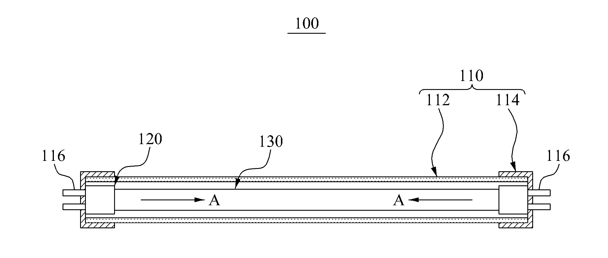
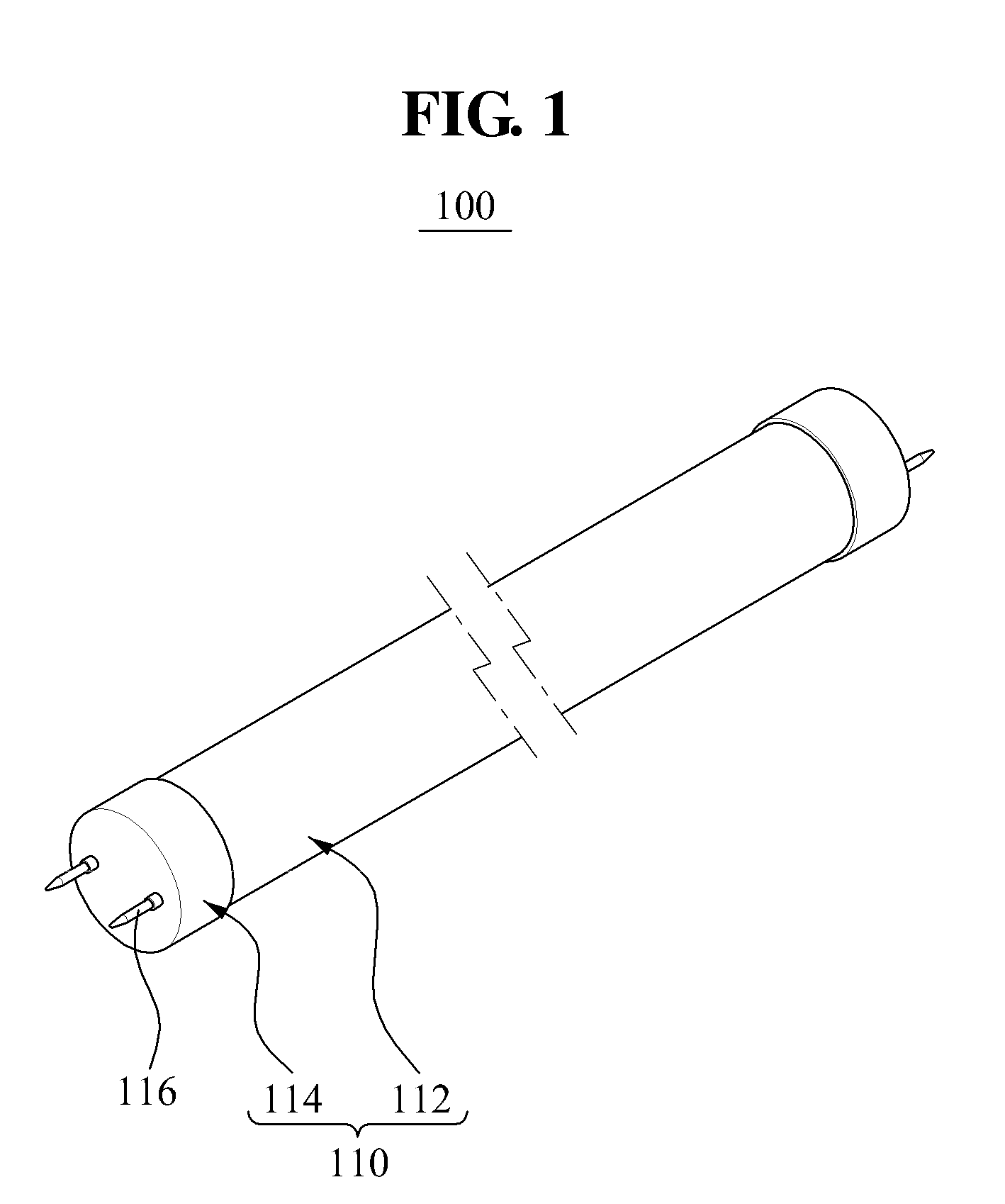
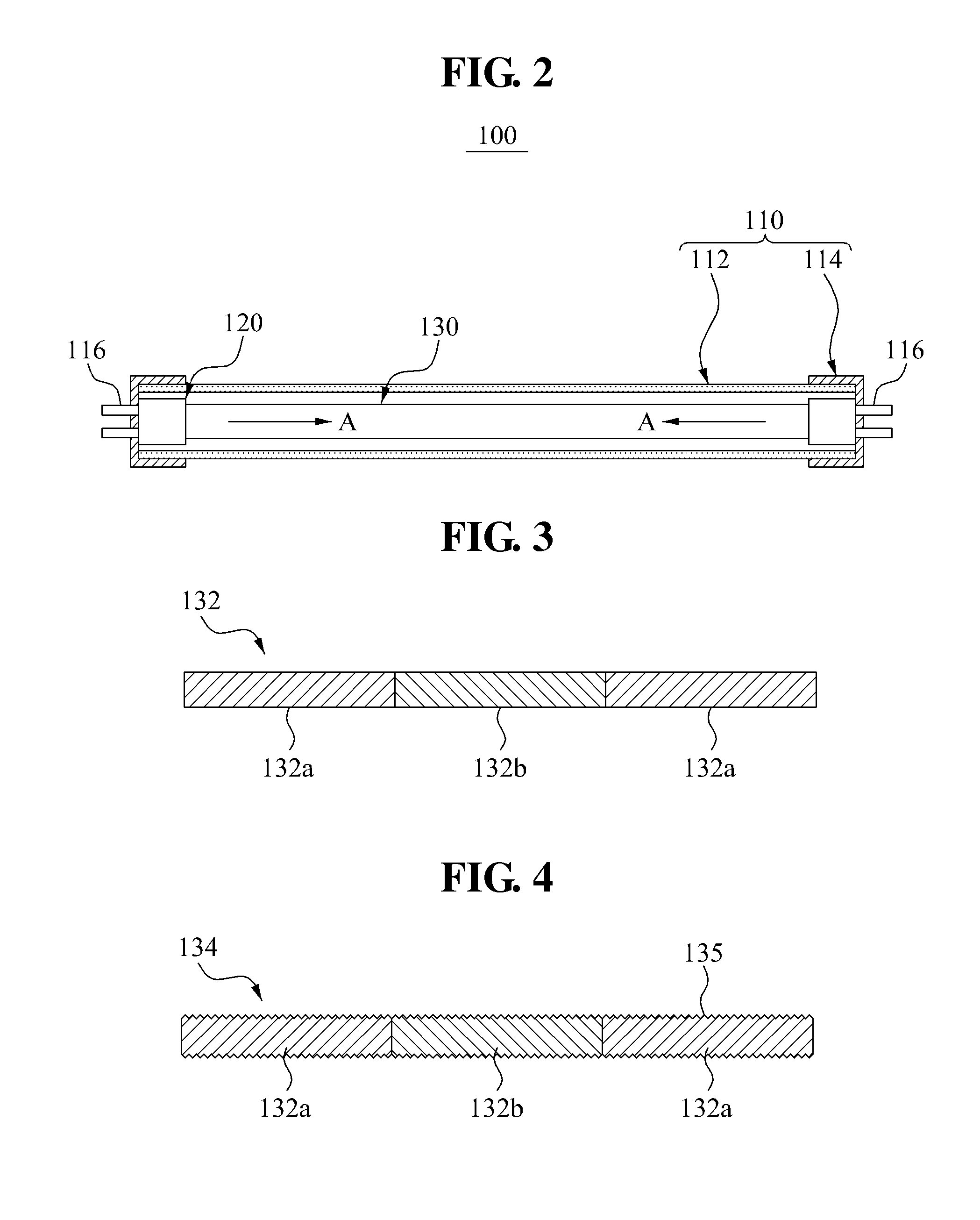
[0044]FIG. 1 is a perspective view illustrating a lighting device 100 according to an embodiment. FIG. 2 illustrates a structure of the lighting device 100 shown in FIG. 1. FIG. 3 is a sectional view illustrating an example of a light guide member 130 shown in FIG. 2. FIG. 4 is a sectional view illustrating another example of the light guide member 130 shown in FIG. 2. FIG. 5 is a cross-sectional view illustrating yet another example of the light guide member 130 shown in FIG. 2.

[0045]Referring to FIGS. 1 and 2, the lighting device 100 includes a device main body 110, a light emitting diode (LED) 120, and the light guide member 130.

[0046]The device main body 110 may include a fluorescent tube 112 and a support member 114....


PUM


Abstract

A lighting device improves light distribution uniformity. When a light emitting diode (LED) package module is applied to a straight-tube fluorescent lamp, characteristics of a circular surface light source with the LED may be efficiently embodied by varying a refractive index of a light guide member based on positions of the light guide member.

Description


Claims


Application Information

Patent Timeline
Owner SAMSUNG ELECTRONICS CO LTD
Why Eureka
Try Eureka