Enhanced medical device for use in bodily cavities, for example an atrium

a medical device and atrium technology, applied in the field of surgery, can solve the problems of increasing the complexity of the device structure, increasing the difficulty of deployment, and doctors not having direct visual contact with the medical device, so as to improve the positioning and performance of ablation, and enhance the capability of deployment

Active Publication Date: 2013-07-04
KARDIUM
View PDF5 Cites 84 Cited by
  • Summary
  • Abstract
  • Description
  • Claims
  • Application Information

AI Technical Summary

Benefits of technology

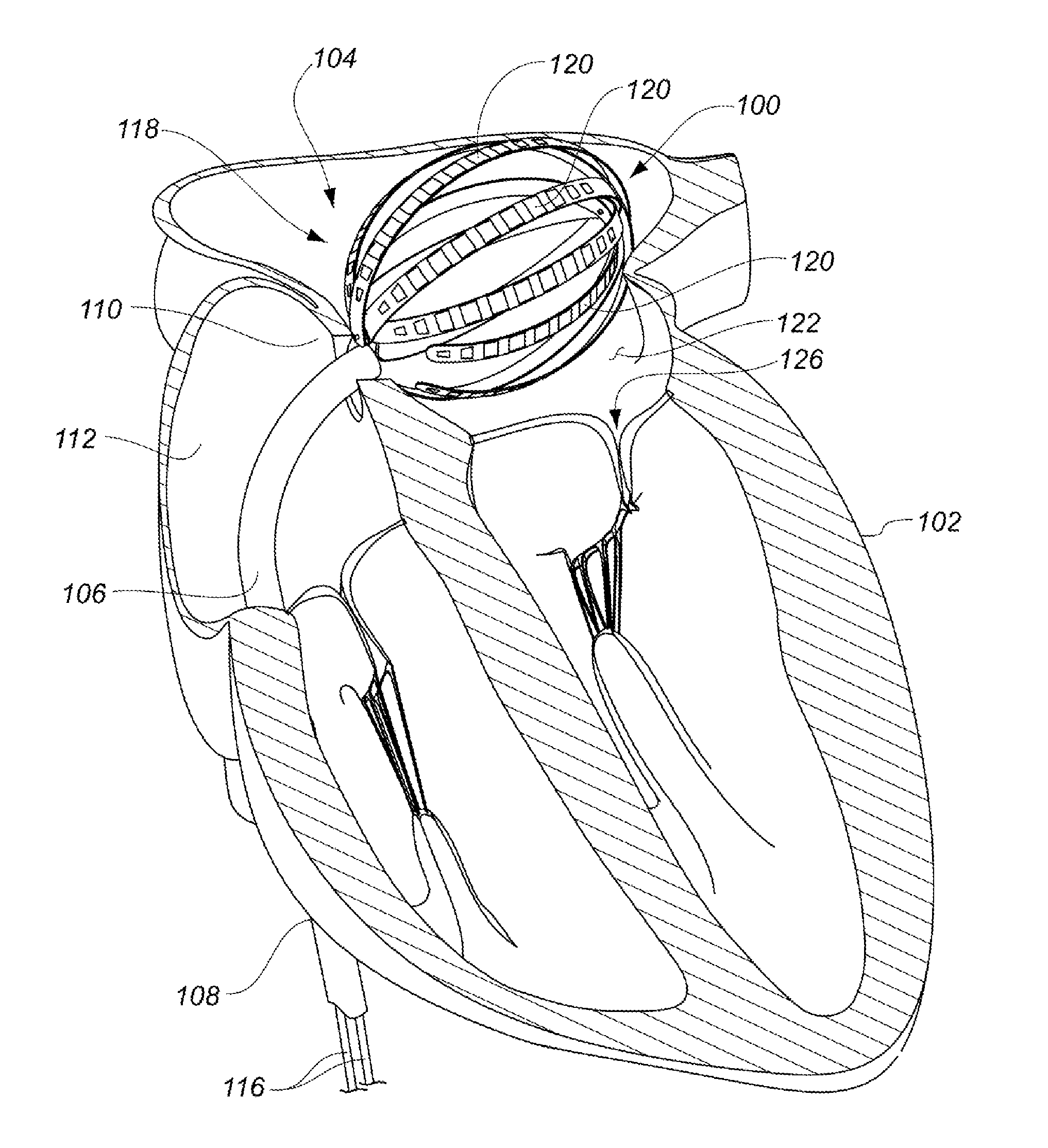
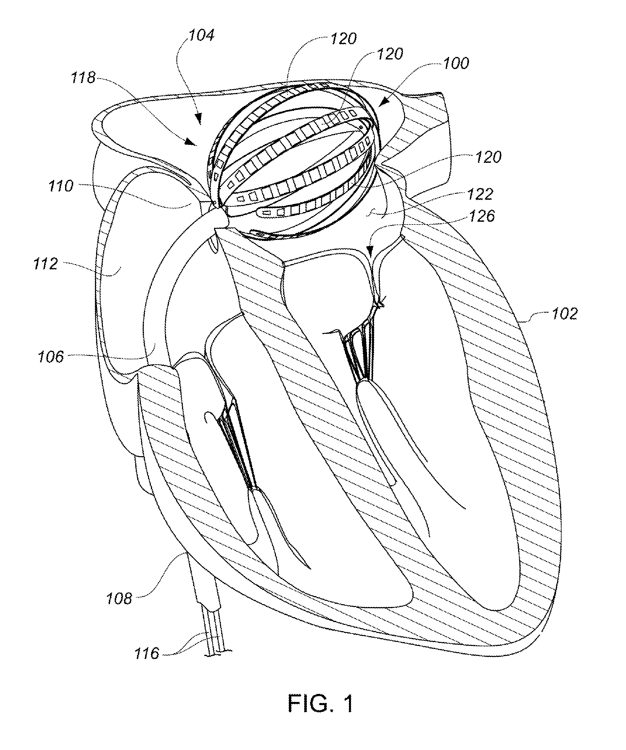
[0015]The present design of a medical device with enhanced capabilities for deployment, positioning and ablating within a bodily cavity such as an intra-cardiac cavity is disclosed. In particular, the device is configurable from a first or unexpanded configuration in which a portion of the device is sized for delivery to a bodily cavity via a catheter sheath to a second or expanded configuration in which the portion of the device is expanded to position various transducer elements at least proximate a tissue surface within the bodily cavity. The device may employ a method for distinguishing tissue from blood and may be used to deliver positional information of the device relative to ports in the atrium, such as the pulmonary veins and mitral valve. The device may employ characteristics such as blood flow detection, impedance change detection or deflection force detection to discriminate between blood and tissue. The device may also improve ablation positioning and performance by ablating using the same elements used for discriminating between blood and tissue. Other advantages will become apparent from the teaching herein to those of skill in the art.
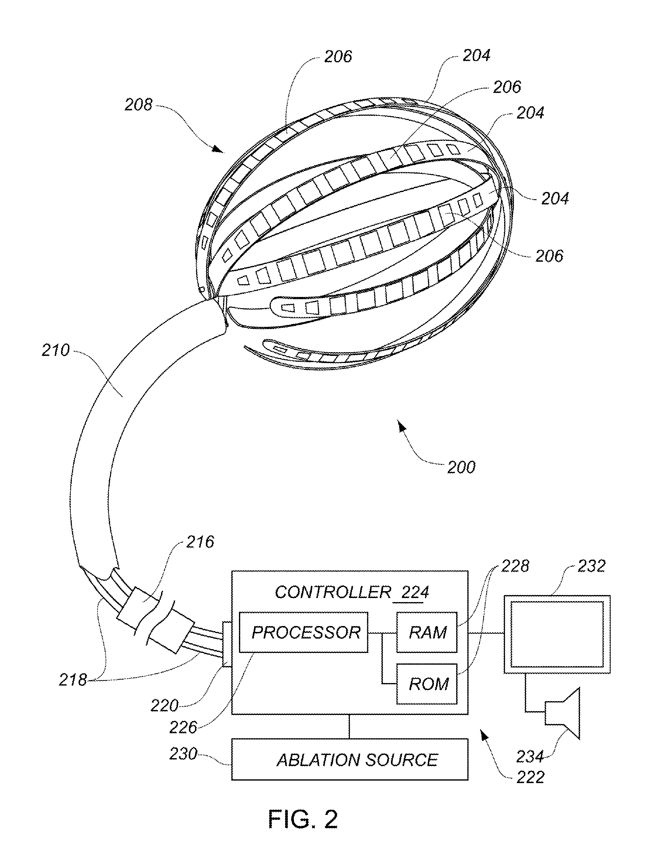
[0117]A medical system may be summarized as including a structure that includes a plurality of elongate members. Each elongate member of the plurality of elongate members includes a plurality of ends including a proximal end and a distal end. Each elongate member of the plurality of elongate members further includes a respective intermediate portion positioned between the proximal and the distal ends of the elongate member, and a respective length between the proximal and the distal ends of the elongate member. The structure further includes a plurality of couplers arranged to physically couple each elongate member of the plurality of elongate members together with at least one other elongate member of the plurality of elongate members at each of at least two spaced apart locations along the respective length of the elongate member of the plurality of elongate members. A method employing the medical system may be summarized as including providing a catheter sheath that includes a first end, a second end and a lumen extending therebetween, and arranging the structure to have a size suitable for delivery though the lumen of the catheter sheath, each of the elongate members in the structure arranged to be advanced distal end first out from the lumen of the catheter sheath. The method includes expanding the structure to have a size too large for delivery through the lumen of the catheter sheath. The method includes providing at least one of a) relative movement between at least some of the ends in a first set of the proximal ends of the elongate members of the plurality of elongate members to reduce an end-to-end distance between the at least some of the ends in the first set during the expanding or b) relative movement between at least some of the ends in a second set of the distal ends of the elongate members of the plurality of elongate members to reduce an end-to-end distance between the at least some of the ends in the second set during the expanding.
[0125]The portion of the structure may include the respective curved portion of the at least one of the at least some of the plurality of elongate members when the structure is in the deployed configuration. The first axis may pass through the at least one of the at least some of the plurality of elongate members at a first location spaced along the respective length of the at least one of the at least some of the plurality of elongate members from one of the respective proximal end and the respective distal end of the at least one of the at least some of the plurality of elongate members, and the at least one actuator may be operably coupled to the structure to selectively reduce the curvature of the respective curved portion of the at least one of the at least some of the plurality of elongate members to reduce a distance between the first location and the one of the respective proximal end and the respective distal end of the at least one of the at least some of the plurality of elongate members when the structure is in the deployed configuration.

Problems solved by technology

However, the use of intravascular or percutaneous technologies also raises some particular challenges.
Medical devices used in intravascular or percutaneous surgery need to be deployed via catheter systems which significantly increase the complexity of the device structure.
As well, doctors do not have direct visual contact with the medical devices once the devices are positioned within the body.
Positioning these devices correctly and operating the devices successfully can often be very challenging.
The procedure is performed with a high success rate under the direct vision that is provided in open procedures, but is relatively complex to perform intravascularly or percutaneously because of the difficulty in creating the lesions in the correct locations.
Various problems, potentially leading to severe adverse results, may occur if the lesions are placed incorrectly.
Additional challenges therefore exist in creating a device that can assume an unexpanded configuration for passage through these smaller sheaths and yet, can also assume an expanded configuration suitable for positioning a portion of the device proximate to a tissue surface within the cavity.

Method used


Image

  • Enhanced medical device for use in bodily cavities, for example an atrium
  • Enhanced medical device for use in bodily cavities, for example an atrium
  • Enhanced medical device for use in bodily cavities, for example an atrium

Examples


Embodiment Construction

[0199]In the following description, certain specific details are set forth in order to provide a thorough understanding of various embodiments of the invention. However, one skilled in the art will understand that the invention may be practiced without these details. In other instances, well-known structures associated with Radio Frequency (RF) ablation and electronic controls such as multiplexers have not been shown or described in detail to avoid unnecessarily obscuring descriptions of the embodiments of the invention.

[0200]The word “ablation” should be understood to mean any disruption to certain properties of the tissue. Most commonly, the disruption is to the electrical conductivity and is achieved by heating, which can be generated with resistive or of Radio Frequencies (RF) techniques for example. Other properties, such as mechanical or chemical, and other means of disruption, such as optical, are included when the term “ablation” is used.

[0201]The word “fluid” should be unde...


PUM


Abstract

Systems, methods, and devices allow intravascular or percutaneous mapping, orientation or ablation, or combinations thereof in bodily cavities or lumens. A device includes a plurality of elongate members which are moveable between an unexpanded configuration, a bent or coiled stack configuration and an expanded or fanned configuration. The elongate members form a stack arrangement in the unexpanded configuration to fit through a catheter sheath, The elongate members follow respective arcuate or curvilinear paths as advanced from the sheath into the bent or coiled stack configuration, adopting volute, scroll or rho shapes, and may be nested. The elongated members are fanned or radially spaced circumferentially with respect to one another into the expanded or fanned configuration. Transducers carried by elongate members may sense various physiological characteristics of or proximate tissue, for instance temperature, and / or may apply energy to or proximate tissue, for example to perform ablation. The device is retractable.

Description

BACKGROUND[0001]1. Technical Field[0002]This disclosure is generally related to surgery, and more particularly to intravascularly or percutaneously deployed medical devices suitable for determining locations of cardiac features or ablating regions of cardiac tissue, or both.[0003]2. Description of the Related Art[0004]Cardiac surgery was initially undertaken using highly invasive open procedures. A sternotomy, which is a type of incision in the center of the chest that separates the sternum (chest bone) was typically employed to allow access to the heart. In the past several decades, more and more cardiac operations are performed using intravascular or percutaneous techniques, where access to inner organs or other tissue is gained via a catheter.[0005]Intravascular or percutaneous surgeries benefit patients by reducing surgery risk, complications and recovery time. However, the use of intravascular or percutaneous technologies also raises some particular challenges. Medical devices ...

Claims


Application Information

Patent Timeline
Patent Type & Authority Applications(United States)
IPC IPC(8): A61B18/18
CPCA61B5/0538A61B2019/465A61M25/0082A61B5/6843A61B5/6858A61B5/026A61B5/0422A61B5/06A61B18/1492A61B2018/0016A61B2018/00267A61B2018/00351A61B2018/00357A61B2018/00577A61B2018/00791A61B2018/00839A61B2018/00863A61B2018/00875A61M25/0074A61B2090/065A61B5/065A61B5/287A61B18/00
Inventor LOPES, FERNANDOMOISA, SAARJARAMILLO, JORGEGOERTZEN, DOUGLASHAWES, PETERSARDARI, ASHKANSALVESTRO, ALDO ANTONIO
Owner KARDIUM
Why Eureka
Try Eureka