System for direct engraving of flexographic printing members

a technology of flexographic printing and engraving system, which is applied in the field of flexographic printing, can solve the problems of reducing the sensitivity of heat ablation, reducing the heat ablation rate, so as to improve the heating uniformity and ablation sensitivity, the effect of reducing the amount of hea

Inactive Publication Date: 2015-01-27
MIRACLON CORP
View PDF58 Cites 0 Cited by
  • Summary
  • Abstract
  • Description
  • Claims
  • Application Information

AI Technical Summary

Benefits of technology

[0030]Laser absorbing materials can be organic dyes or pigments, inorganic dyes or pigments or more typically carbon particles. In an ablation sensitive composition there is usually an optimum absorber concentration where too little results in poor ablation due to insufficient coupling of the laser radiation to heat and too much absorber limits ablation due to its bulk cohesive properties or by confining the heating to too thin a region at the surface. The bulk of the elastomeric printing element is typically formulated to have close to the optimum absorber concentration to maximize efficiency and through put. It may also be formulated to have a gradient absorber concentration designed to improve heating uniformity and ablation sensitivity.
[0031]In one embodiment of the invention the thin top-most engraving control layer contains less laser radiation absorber than the underlying layer reducing the amount of heat that can be coupled into the top layer at a given exposure. In another embodiment of the invention the thin top layer contains significantly more laser radiation absorber than is present in the underlying material reducing the effectiveness of laser ablation of the thin top layer and therefore the laser ablation sensitivity is lower. In another embodiment of the invention the thin top layer contains polymers that are less easily ablated than those used in the underlying composition. This can be achieved, for example, by having more extensively cross linked polymers in the top layer. In yet another embodiment of the invention the thin top layer contains more laser ablation insensitive filler materials than is present in the underlying material reducing the effectiveness of laser ablation of the thin top layer. Any combination of the above compositional differences can be used to control the engraving sensitivity of the thin top layer compared to the underlying composition provided that the top layer can be ablated when sufficient exposure is provided by the engraving system.
[0032]On press, the gap between the impression cylinder and a receiver element is adjusted to optimize print density and image quality. This gap is referred to as the engagement and creates the inking pressure (also known as “impression pressure”) between the flexographic printing member and the receiver element to be printed. There is another gap controlled separately on press between the impression cylinder and the Anilox roller used to ink the member, also referred to as engagement. It is an aim of the current invention to reduce the offset of the topmost surface of features in the fine-featured regions and the topmost surface of the flexographic printing member such that the small features in the fine-featured region make sufficient contact with the Anilox roller to be properly inked and make sufficient contact to a receiver element to effectively and uniformly transfer of ink under the normal range of flexographic press conditions and engagement settings.

Problems solved by technology

“Natural” undercutting results from undesirable exposure at the tops of fine features during the laser ablation process due to the overlap of the laser spots spaced close to the feature or due to the partial exposure during modulation in the fast scan direction when high screen rulings are used.
Amplitude modulation of the laser spots close to the fine features can be used to minimize the unwanted exposure but does not eliminate it.
The exposure levels are much lower than those used to create the floor relief but nevertheless result in ablative erosion of the tops of the fine features (i.e. “natural” undercutting).
It can contain voids, hollow beads or porous beads but in this case would typically have higher density (i.e. less voided volume) than the underlying composition rendering it more difficult to ablate.
In an ablation sensitive composition there is usually an optimum absorber concentration where too little results in poor ablation due to insufficient coupling of the laser radiation to heat and too much absorber limits ablation due to its bulk cohesive properties or by confining the heating to too thin a region at the surface.

Method used


Image

  • System for direct engraving of flexographic printing members
  • System for direct engraving of flexographic printing members
  • System for direct engraving of flexographic printing members

Examples


Embodiment Construction

Definitions

[0040]The following definitions identify various terms and phrases used in this disclosure to define the present invention. Unless otherwise noted, these definitions are meant to exclude other definitions of the terms or phrases that may be found in the prior art.

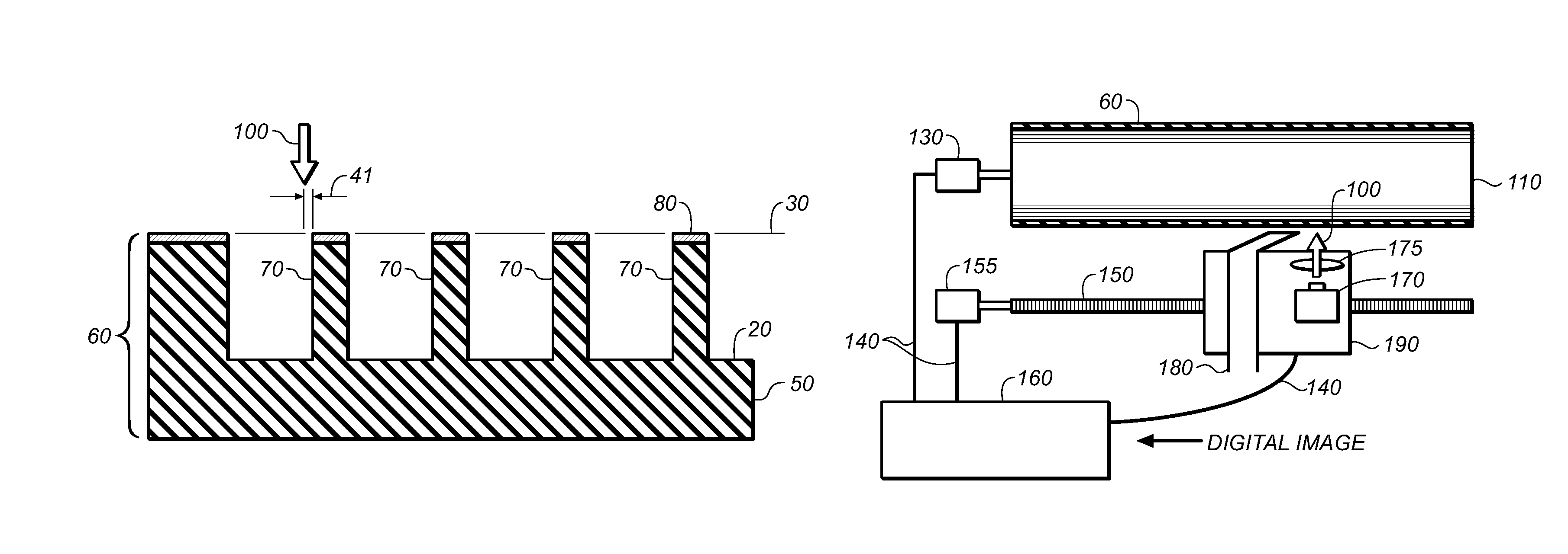
[0041]The term “flexographic printing precursor” refers to the material that is used to prepare the flexographic printing member of this invention and can be in the form of flexographic printing plate precursors, flexographic printing cylinder precursors, and flexographic printing sleeve precursors.

[0042]The term “flexographic printing member” refers to articles of the present invention that are imaged flexographic printing precursors and can be in the form of a printing plate having a substantially planar elastomeric topmost surface, or a printing cylinder or seamless printing sleeve having a curved elastomeric topmost surface. In the case of sleeves and cylinders heights and levels are, of course, in reference ...


PUM

PropertyMeasurementUnit
thicknessaaaaaaaaaa
depthaaaaaaaaaa
thicknessaaaaaaaaaa

Abstract

A system for engraving a flexographic relief member includes a laser scanning apparatus providing a focused radiation beam. The flexographic relief member includes a laser engraveable flexographic member; a thin engraveable control layer on top of the flexographic member; and wherein the engraveable control layer has an engraving sensitivity lower than the flexographic member.

Description

CROSS REFERENCE TO RELATED APPLICATIONS[0001]Reference is made to commonly-assigned copending U.S. patent application Ser. No. 13 / 448,435, filed Apr. 17, 2012, entitled METHOD FOR DIRECT ENGRAVING OF FLEXOGRAPHIC PRINTING MEMBERS, by Burberry et al.; the disclosure of which is incorporated herein.FIELD OF THE INVENTION[0002]This invention relates to the field of flexographic printing. More particularly, this invention relates to an improved system for preparing flexographic printing members using direct engraving methods. The flexographic printing members exhibit improved dot gain control and uniformity.BACKGROUND OF THE INVENTION[0003]Flexography is a method of printing that is commonly used for high-volume relief printing runs on a variety of substrates such as paper, paper stock board, corrugated board, polymeric films, labels, foils, fabrics, and laminates. Flexographic printing has found particular application in packaging, where it has displaced rotogravure and offset lithogra...

Claims


Application Information

Patent Timeline
Patent Type & Authority Patents(United States)
IPC IPC(8): B23K26/00B41C3/08B41N1/00B28B17/00
CPCB41C1/05B41N1/12
Inventor BURBERRY, MITCHELL S.TUTT, LEE W.ROWLEY, LAWRENCE A.
Owner MIRACLON CORP
Why Eureka
Try Eureka