Method for cooling a thermal protection floor of an aft aerodynamic fairing of a structure for mounting an aircraft propulsion system

a technology for mounting structures and propulsion systems, which is applied in the direction of efficient propulsion technologies, machines/engines, transportation and packaging, etc., can solve the problems of increasing the temperature of the primary airstream and the noise of the j

Active Publication Date: 2013-07-11
AIRBUS OPERATIONS (SAS)
View PDF5 Cites 10 Cited by
  • Summary
  • Abstract
  • Description
  • Claims
  • Application Information

AI Technical Summary

Problems solved by technology

Secondly, the mounting structure is fitted with mounting means interposed between the engine and the rigid structure.
This increase of temperature of the primary airstream poses many problems, notably with regard to thermal resistance and thermal expansion of the materials forming the thermal protection floor, and also to the noise of the jet, which tends to be intensified as a consequence.
This phenomenon is particularly pronounced when the aft aerodynamic fairing of the mounting structure extends as an extension of a bifurcation, i.e. from a region isolated from the secondary airstream into which extends a portion of the rigid structure of the mounting structure, and some of the means by which the engine is mounted on this rigid structure, given that such a bifurcation forms an obstacle to the penetration of the secondary airstream in the relatively thin space between the thermal protection floor and the exhaust nozzle.

Method used


Image

  • Method for cooling a thermal protection floor of an aft aerodynamic fairing of a structure for mounting an aircraft propulsion system
  • Method for cooling a thermal protection floor of an aft aerodynamic fairing of a structure for mounting an aircraft propulsion system
  • Method for cooling a thermal protection floor of an aft aerodynamic fairing of a structure for mounting an aircraft propulsion system

Examples


Embodiment Construction

[0016]One aim of the invention is notably to provide a simple, economic and efficient solution to these problems, allowing at least some of the abovementioned disadvantages to be avoided.

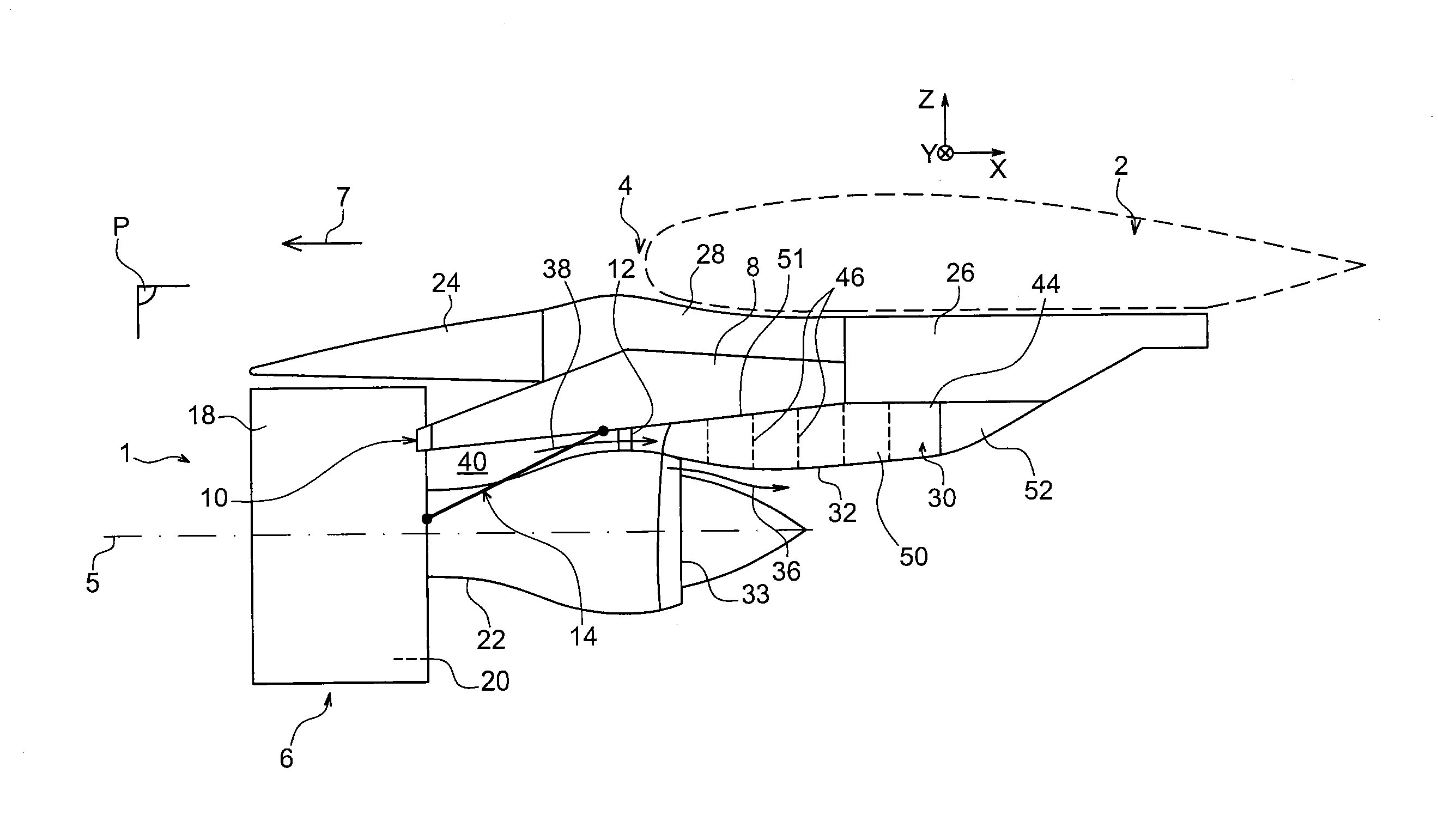
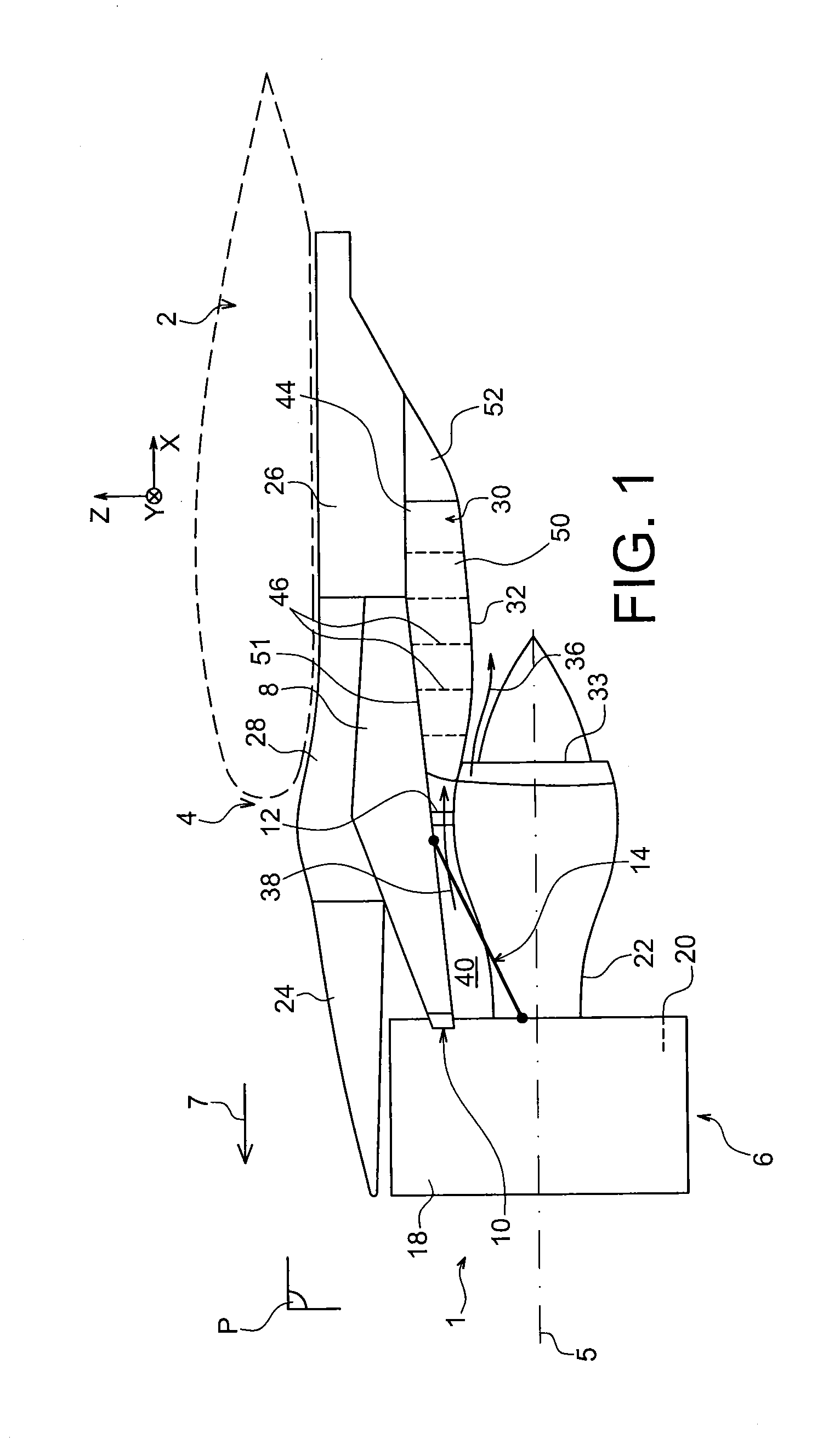
[0017]To this end it proposes a propulsion system for an aircraft having a dual-flow turbojet and a mounting structure intended to mount this turbojet on the wing surface or on the fuselage of an aircraft, where the said mounting structure includes an aft aerodynamic fairing including a thermal protection floor to protect the said mounting structure from the heat of a primary airstream originating from an exhaust nozzle of the said turbojet.

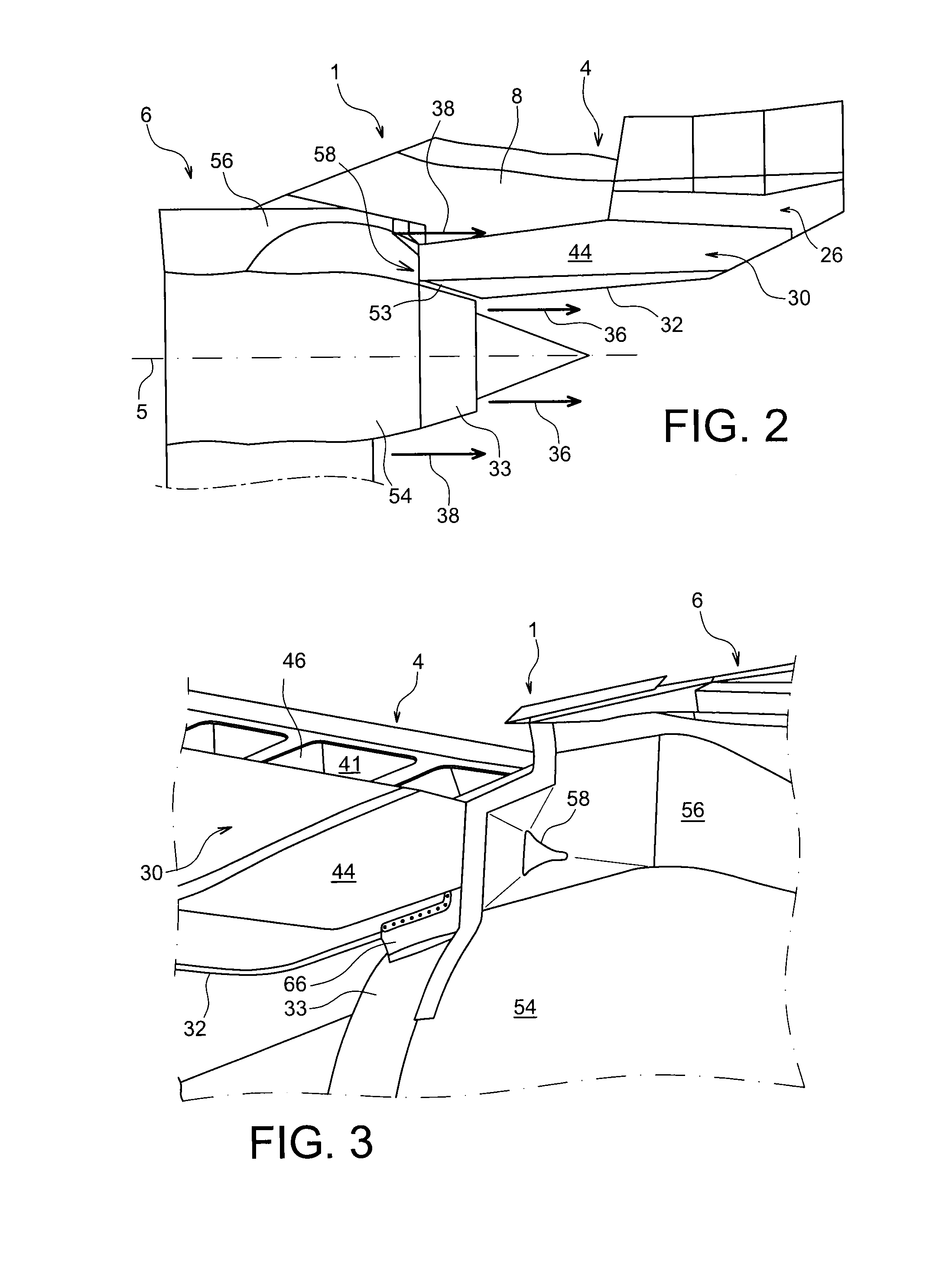
[0018]According to the invention, the propulsion system includes means for extracting a cooling airstream from a secondary airstream of the turbojet, together with air circulation means fed by the said extraction means, and having at least one outlet aperture emerging in a space between the thermal protection floor and the exhaust nozzle.

[0019]The invention thus ...


PUM


Abstract

A propulsion system for an aircraft, including a dual-flow turbojet and a mounting structure for mounting this turbojet on the wing surface or on the fuselage of an aircraft. The mounting structure includes an aft aerodynamic fairing including a thermal protection floor to protect the mounting structure from the heat of a primary airstream channelled by an exhaust nozzle of the turbojet, as well as an air inlet provided in a longitudinal aerodynamic wall washed by a secondary airstream of the turbojet and delimiting together with an other similar wall a cavity isolated from the secondary airstream for extracting a cooling airstream from the secondary airstream, and air circulation means fed by the air inlet and having at least one outlet aperture emerging in a space between the thermal protection floor and the exhaust nozzle.

Description

TECHNICAL FIELD[0001]The present invention relates to the field of aircraft engine mounting structures, and more specifically relates to the thermal protection of a mounting structure for a dual-flow turbojet.[0002]Generally speaking, a mounting structure, also called an Engine Mounting Structure (EMS), allows an engine to be suspended beneath the wing surface of an aircraft, or allows this engine to be mounted above this same wing surface or, again, allows this engine to be mounted in the aft portion of the aircraft's fuselage.STATE OF THE PRIOR ART[0003]Such a mounting structure is designed to form the connecting interface between an engine and a wing surface of the aircraft. It enables the forces generated by its associated engine to be transmitted to the structure of this aircraft, and also allows the routing of fuel, electrical, hydraulic and air systems between the engine and the aircraft.[0004]To transmit the forces the mounting structure includes a rigid structure, also call...

Claims


Application Information

Patent Timeline
Patent Type & Authority Applications(United States)
IPC IPC(8): F01D25/14
CPCB64C7/02B64D29/00B64D33/06F02K1/822B64D33/04F05D2260/20F01D25/14Y02T50/676F02C7/20Y02T50/60
Inventor RAISON, FABIENDUMONT, EMMANUELLE
Owner AIRBUS OPERATIONS (SAS)
Why Eureka
Try Eureka