System and method for determination of transpulmonary pressure in a patient connected to a breathing apparatus

a technology for transpulmonary pressure and patient, which is applied in the direction of respiratory masks, sensors, medical devices, etc., can solve the problems of increased risk of inducing damage to sensitive lung tissue by ventilator treatment, low transpulmonary pressure, and limited lung expansion, so as to achieve accurate determination of ptp

Active Publication Date: 2013-07-11
THE LUNG BAROMETRY SWEDEN
View PDF6 Cites 15 Cited by
  • Summary
  • Abstract
  • Description
  • Claims
  • Application Information

AI Technical Summary

Benefits of technology

[0038]In summary, ΔEELV/ΔPEEP provides a calculation value for CL. This is provided for the pressure/volume range in which a PEEP step is performed. A most advantageous measurement is based on spirometric determination of the ingoing calculation parameters. At small PEEP steps and volumes, the value is at an optimum. Small PEEP steps are in this context up to 3 ...

Problems solved by technology

For instance, the risk of inducing damage to the sensitive lung tissue by the ventilator treatment is increasing when the lung is very stiff and the chest wall/diaphragm is very soft, where most of the airway pressure generated by the ventilator during inspiration acts solely on the lung, i.e. a high transpulmonary pressure is present.
On the other hand, in a case where the stiffness of the chest wall and especially the diaphragm is increased, e.g. by abdominal inflammation, with resulting high sub-diaphragmatic pressures, the lung will be limited in its expansion by the stiffness of the chest wall and diaphragm, and the transpulmonary pressure will be low.
As measurement of the transpulmonary pressure is difficult, a measurement of the oesophageal pressure is used as a surrogate of pleural pressure instead of measuring pleural pressure directly.
However, there are practical difficulties of performing the oesophageal pressure measurement.
The correct placement of the oesophageal balloon catheter in the oesophag...

Method used


Image

  • System and method for determination of transpulmonary pressure in a patient connected to a breathing apparatus
  • System and method for determination of transpulmonary pressure in a patient connected to a breathing apparatus
  • System and method for determination of transpulmonary pressure in a patient connected to a breathing apparatus

Examples


Embodiment Construction

[0055]Specific embodiments of the invention will now be described with reference to the accompanying drawings. This invention may, however, be embodied in many different forms and should not be construed as limited to the embodiments set forth herein; rather, these embodiments are provided so that this disclosure will be thorough and complete, and will fully convey the scope of the invention to those skilled in the art. The terminology used in the detailed description of the embodiments illustrated in the accompanying drawings is not intended to be limiting of the invention. In the drawings, like numbers refer to like elements.

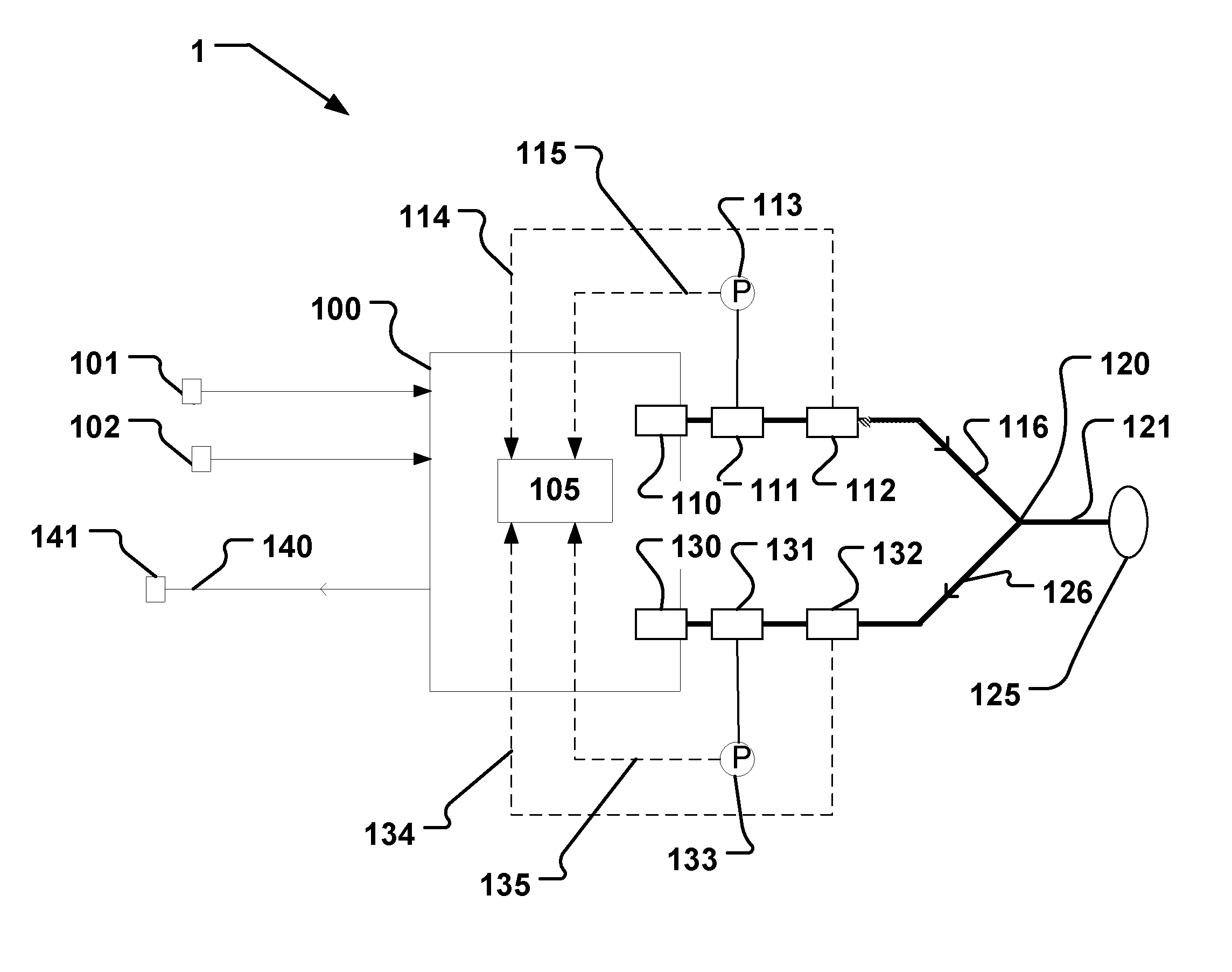
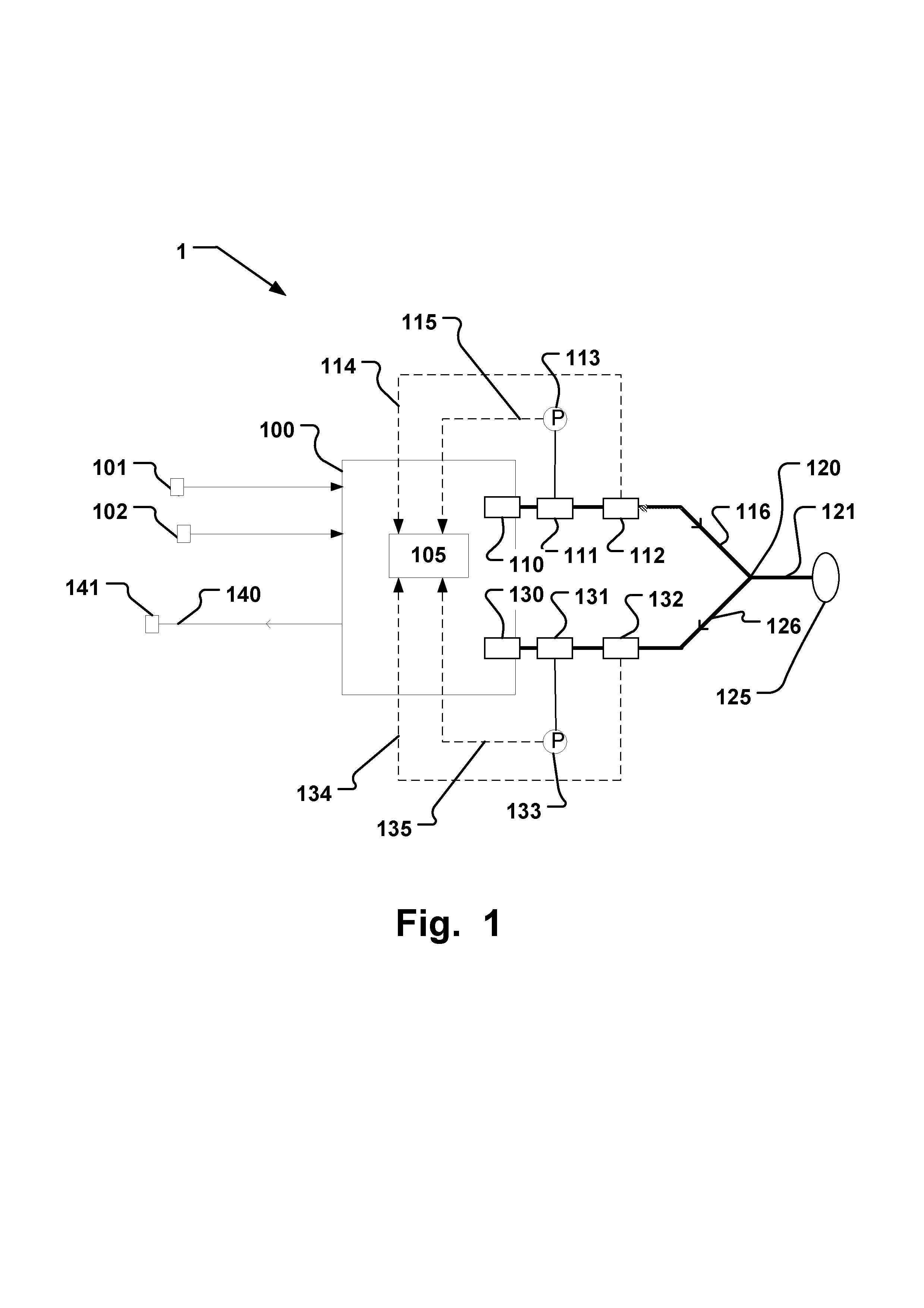
[0056]The following description describes an embodiment applicable to a breathing apparatus and in particular to a respiratory ventilator in use connected to sources of pressurized gas. However, it will be appreciated that the invention is not limited to this application but may be applied to many other breathing apparatuses, including for example fan driven b...


PUM


Abstract

A breathing apparatus (1) is disclosed that is adapted to determine a transpulmonary pressure in a patient (125) when connected to said breathing apparatus. A control unit (105) is operable to set a first mode of operation for ventilating said patient with a first Positive End Expiratory Pressure (PEEP) level; set a second mode of operation for ventilating said patient with a second PEEP level starting from said first PEEP level; and determine said transpulmonary pressure (Ptp) based on a change in end-expiratory lung volume (ΔEELV) and a difference between said first PEEP level and said second PEEP level (ΔPEEP). Furthermore, a method and computer program are disclosed.

Description

RELATED APPLICATIONS[0001]This application claims priority to U.S. Provisional Patent Application Ser. No. 61 / 356,589, and European Patent Application EP10166587, filed both filed Jun. 19, 2010, and U.S. Provisional Patent Application Ser. No. 61 / 469,100 filed Mar. 30, 2011, all entitled “A system and method for determination of transpulmonary pressure in a patient connected to a breathing apparatus”, which are hereby incorporated herein by reference in their entirety for all purposes.BACKGROUND OF THE INVENTION[0002]Patients with acute respiratory failure in need for ventilator treatment in intensive care units show highly varying pathophysiologic conditions of the respiratory system. With regard to the heterogeneity of acute lung injury (ALI) and the more severe acute respiratory distress syndrome (ARDS), the percentage of potentially recruitable lung, i.e. lung tissue that was collapsed but can be opened by a high pressure inflation is up to approximately 60%. One important reaso...

Claims


Application Information

Patent Timeline
IPC IPC(8): A61M16/00
CPCA61B5/08A61M16/205A61M16/0051A61M16/12A61M2016/0021A61M2016/0027A61M2016/0039A61M2016/0042A61M2205/3331A61M2230/46A61M16/0057A61B5/7282A61B5/7278A61B5/7225A61B5/4836A61B5/097A61M16/208A61B5/085A61M16/0069A61M16/0003A61M16/06A61B5/0871A61M16/204A61B5/091A61M2210/105A61M16/026
Inventor STENQVIST, OLA
Owner THE LUNG BAROMETRY SWEDEN
Why Eureka
Try Eureka