Valve positioning system with bleed prevention

a valve positioning and valve technology, applied in the direction of flow control, water supply installation, gas/liquid distribution and storage, etc., can solve the problems of high cost, high cost, and high cost of additional external components of such valves, and achieve low flow coefficient (cv)

Active Publication Date: 2013-07-11
SUBARU TECNICA INTERNATIONAL
View PDF8 Cites 13 Cited by
  • Summary
  • Abstract
  • Description
  • Claims
  • Application Information

AI Technical Summary

Problems solved by technology

These additional external components tend to be costly, and require a safe external power source with associated connectivity components.
In general, there are additional complications and costs, particularly for deployment in hazardous environments.
However, the flow coefficient (Cv) of such valves is low, and oftentimes necessitate boosters for meeting stroking time requirements of most typical deployments.
Furthermore, such boosters are also understood to exhibit some degree of leakage, largely negating the advantages of normally closed valves.

Method used


Image

  • Valve positioning system with bleed prevention
  • Valve positioning system with bleed prevention
  • Valve positioning system with bleed prevention

Examples


Embodiment Construction

[0025]The detailed description set forth below in connection with the appended drawings is intended as a description of certain embodiments of an electro-pneumatic valve positioner having steady-state zero bleed capabilities and is not intended to represent the only forms that may be developed or utilized. The description sets forth the various functions in connection with the illustrated embodiments, but it is to be understood, however, that the same or equivalent functions may be accomplished by different embodiments that are also intended to be encompassed within the scope of the present disclosure. It is further understood that the use of relational terms such as first and second, and the like are used solely to distinguish one entity from another without necessarily requiring or implying any actual such relationship or order between such entities.

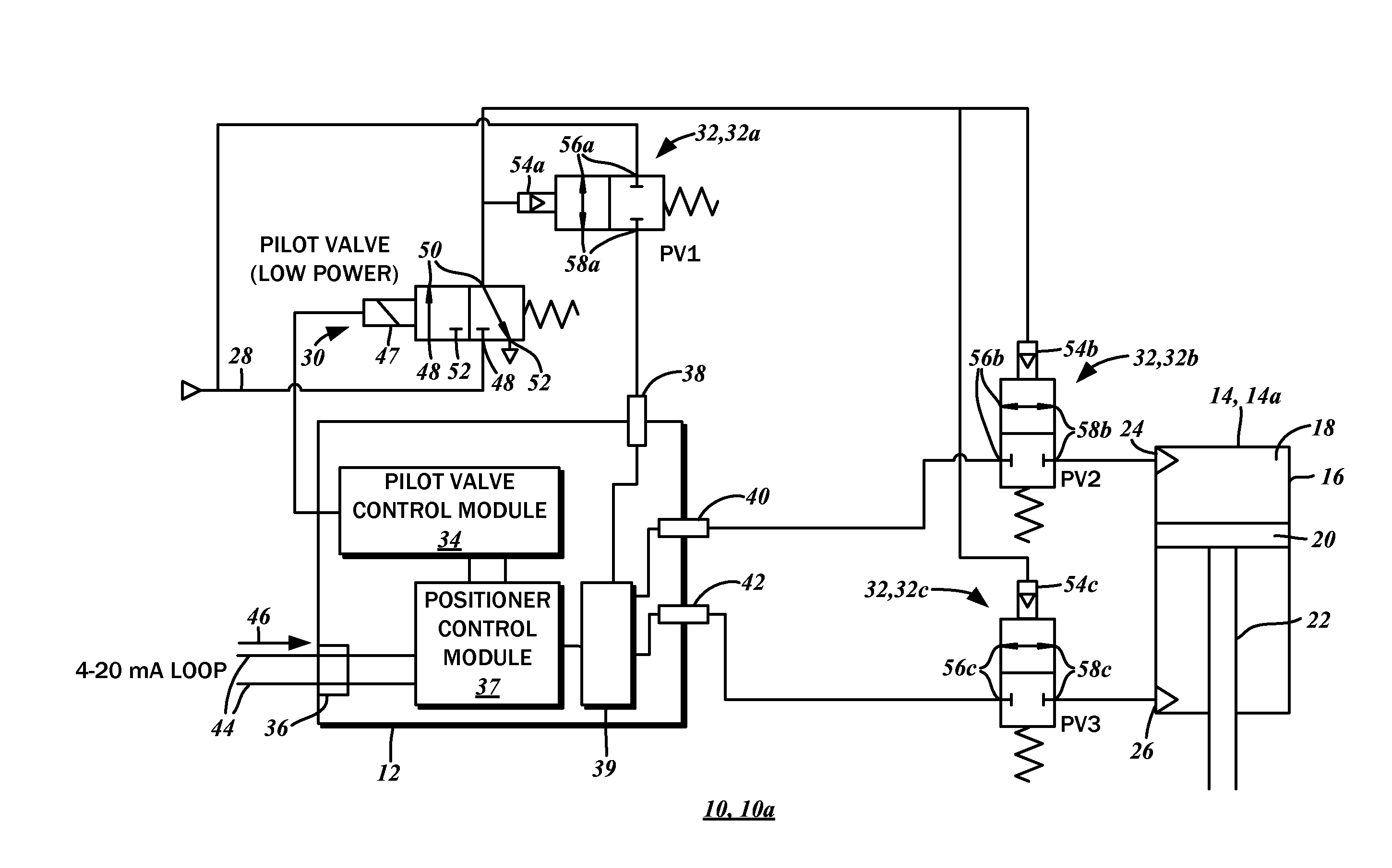
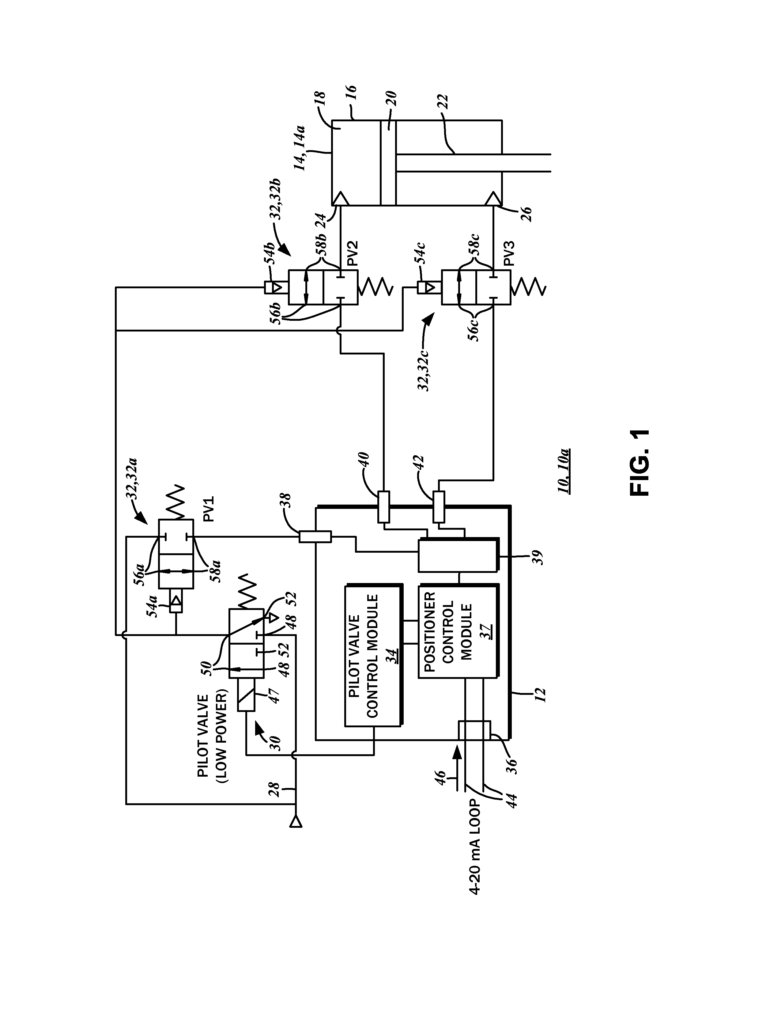
[0026]With reference to the block diagram of FIG. 1, a first embodiment of the valve positioner system 10a with steady-state zero ble...


PUM


Abstract

A valve positioner system with zero bleed at steady state is disclosed. The system has a pilot valve, the operation of which is controlled by an electronic circuit powered from a signaling and power connection of a positioner device. A plurality of pneumatic valves are activated and deactivated by the pilot valve to control a valve actuator. With varying configurations and arrangements of normally open or normally closed pilot valves and pneumatic valves, fail freeze and fail safe operations are contemplated. The activation and deactivation of the pilot valve is controlled by an electronic circuit that monitors a valve position signal.

Description

CROSS-REFERENCE TO RELATED APPLICATIONS[0001]The present application claims priority to U.S. Provisional Patent Application Ser. No. 61 / 581,833 entitled VALVE POSITIONING SYSTEM WITH BLEED PREVENTION filed Dec. 30, 2011.STATEMENT RE: FEDERALLY SPONSORED RESEARCH / DEVELOPMENT[0002]Not ApplicableBACKGROUND OF THE INVENTION[0003]1. Field of the Invention[0004]The present invention relates generally to control systems for industrial processes, and more particularly, to pneumatic valve positioning systems and electrical circuits thereof with steady state gas bleed prevention.[0005]2. Description of the Related Art[0006]Many industrial processes involve the movement of fluid such as gas, steam, water, and chemical compounds. The flow of the fluid is regulated by a control valve that has a passageway that is selectively opened and closed with a movable obstruction or valve element connected to a stem. An actuator, in turn, is connected to the stem, and provides the motive force to open and ...

Claims


Application Information

Patent Timeline
Patent Type & Authority Applications(United States)
IPC IPC(8): G05D7/06
CPCG05D7/0617F15B2211/3057F15B2211/329F15B2211/6303F15B2211/6336F15B20/008F15B2211/7052F15B2211/7053F15B2211/87F15B2211/8752F15B19/005F15B2211/6355F15B5/006Y10T137/0324Y10T137/7761
Inventor TONDOLO, FLAVIOVALOTI, ROBERTO
Owner SUBARU TECNICA INTERNATIONAL
Why Eureka
Try Eureka