Methods and apparatus to form electrical interconnects on ophthalmic devices

Active Publication Date: 2013-07-11
JOHNSON & JOHNSON VISION CARE INC
View PDF16 Cites 33 Cited by
  • Summary
  • Abstract
  • Description
  • Claims
  • Application Information

AI Technical Summary

Benefits of technology

[0015]An important equipment aspect of the methods and apparatus to form electrical interconnections on three dimensional surfaces may include the use of laser tooling. In some exemplary embodiments the laser tooling may be useful to ablate or remove regions of a metallic film or an insulating film in a controllable and programmable manner. In other exemplary embodiments, the laser tooling may be useful to ablate material in appropriately defined three dimensional shapes which will act in the process of creating mask entities for defining the location of interconnects. In some exemplary embodiments, the masks may act as shadow masks, which allow the deposition of films upon insert surfaces only where the mask has penetrations within itself. There may be numerous films that may be consistent with masked deposition, including metallic films, dielectric films, high-k dielectric films, conductive and non-conductive epoxies and other conductive and non-conductive films which may be applied in any suitable manner including a spraying process. In other exemplary embodiments, the masks may be useful for intercepting and imaging light of various forms which may be important to lithographic processes which may include plasma and reactive ion etching, wet chemical etching and other such techniques useful for forming defined interconnections.
[0016]In some exemplary embodiments, the interconnections upon the insert may allow for the connection of a component which may exist in an energized state which is capable of powering other components capable of drawing a current by connection through the defined interconnection. Components may include one or more of a variable optic lens element and a semiconductor device, which may either be located upon or in the insert or otherwise connected to it.

Problems solved by technology

The topology and size of the space defined by the lens structure creates a novel and challenging environment for the definition of various functionality.

Method used


Image

  • Methods and apparatus to form electrical interconnects on ophthalmic devices
  • Methods and apparatus to form electrical interconnects on ophthalmic devices
  • Methods and apparatus to form electrical interconnects on ophthalmic devices

Examples


Embodiment Construction

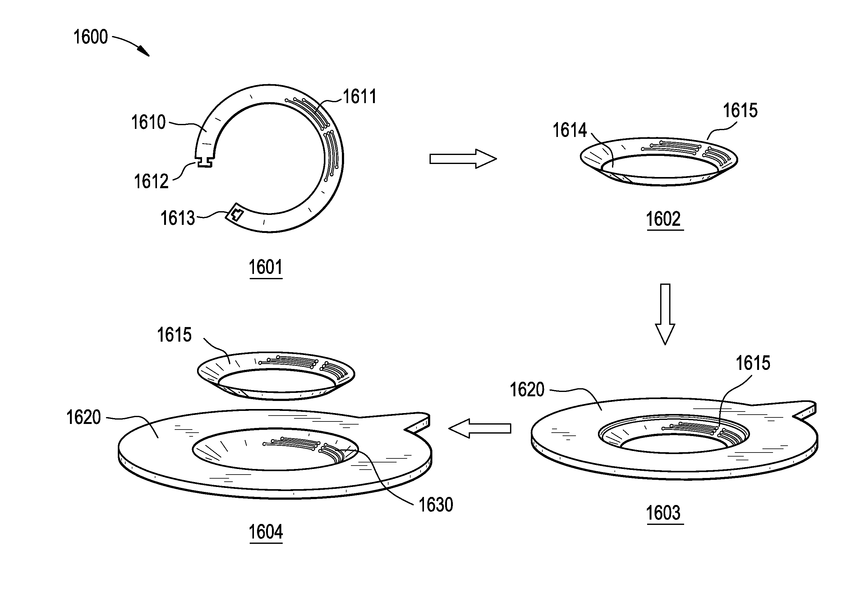
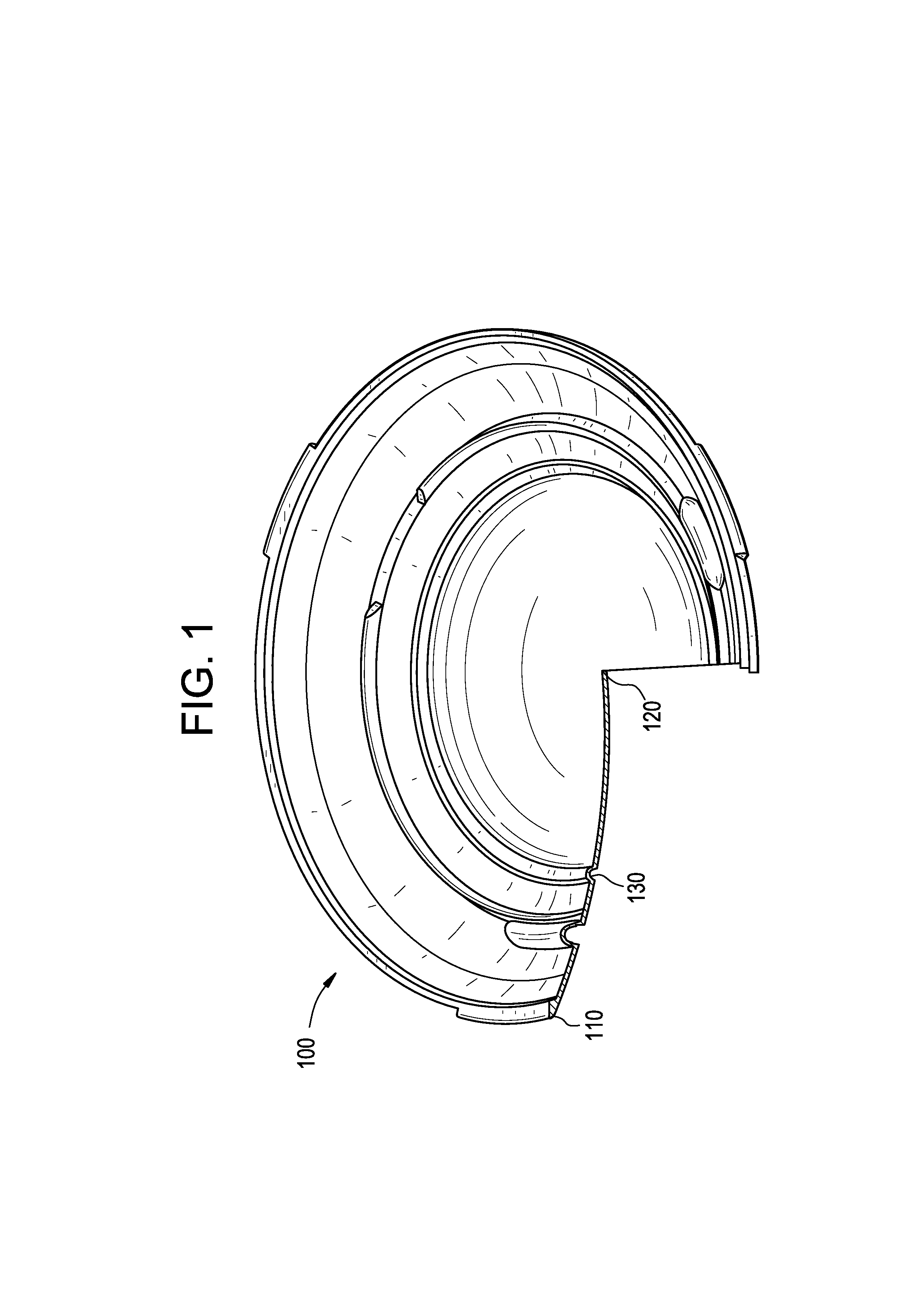
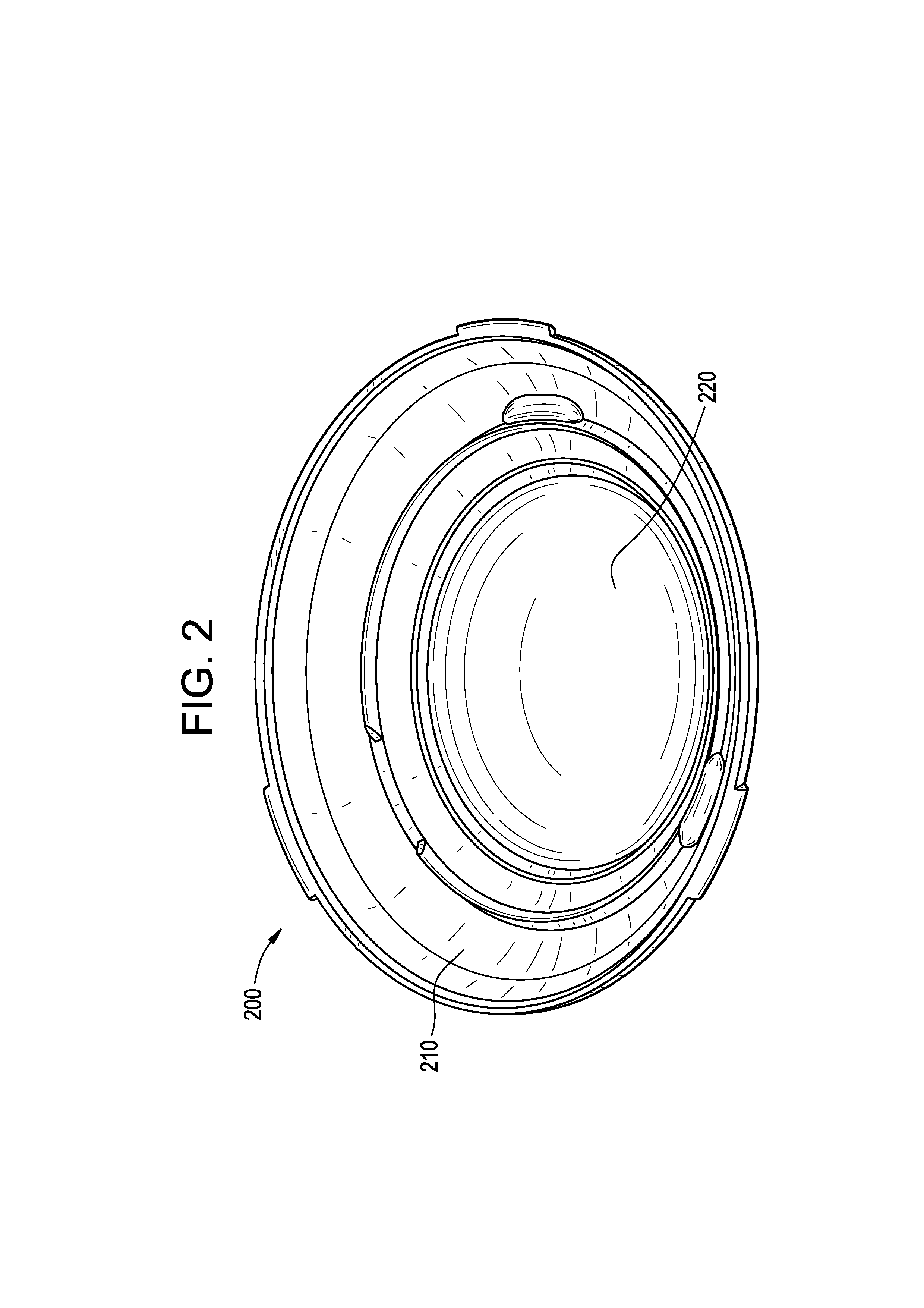
[0036]The present invention relates to methods and apparatus useful in the formation of electrical interconnects upon surfaces that have three dimensional topology. In the following sections, detailed descriptions of exemplary embodiments of the invention will be given. The description of both preferred and alternative embodiments are exemplary embodiments only, and it is understood that to those skilled in the art that variations, modifications and alterations may be apparent. It is therefore to be understood that the exemplary embodiments do not limit the scope of the underlying invention.

[0037]Definitions

[0038]In this detailed description and claims directed to the present invention, various terms may be used for which the following definitions will apply.

[0039]As used herein, the term “energized” refers to the state of being able to supply electrical current to or to have electrical energy stored within.

[0040]As used herein, the term “energy” refers to the capacity of a physical...


PUM

PropertyMeasurementUnit
heightaaaaaaaaaa
heightsaaaaaaaaaa
diametersaaaaaaaaaa

Abstract

Methods and apparatus for forming interconnects on the surfaces of three dimensional substrates, including ophthalmic devices incorporating one or more electrical components may be utilized to provide high quality electrical and mechanical connections.

Description

CROSS REFERENCE TO RELATED APPLICATIONS[0001]This patent application claims the benefit of U.S. Patent Application Ser. No. 61 / 583,693, filed Jan. 6, 2012.BACKGROUND OF THE INVENTION[0002]1. Field of the Invention[0003]The present invention relates to methods and apparatus for forming a device whereon electrical interconnections are configured to connect and physically support attached components or combinations of components. More particularly, the present invention relates to methods and apparatus for forming interconnects on the surfaces of three dimensional substrates, including ophthalmic devices incorporating one or more electrical components.[0004]2. Discussion of the Related Art[0005]Traditionally an ophthalmic device, such as a contact lens, an intraocular lens or a punctal plug included a biocompatible device with a corrective, cosmetic or therapeutic quality. A contact lens, for example, may provide at least one of vision correcting functionality, cosmetic enhancement, an...

Claims


Application Information

Patent Timeline
Patent Type & Authority Applications(United States)
IPC IPC(8): H01R43/00
CPCH01R43/00B29D11/00807H05K1/0284H05K2203/107H05K3/027H05K3/143H05K3/0035A61F9/008A61F9/009
Inventor PUGH, RANDALL B.OTTS, DANIEL B.PANDOJIRAO-S, PRAVEENTONER, ADAMRIALL, JAMES DANIELKERNICK, EDWARD R.BEATON, STEPHEN R.FLITSCH, FREDERICK A.
Owner JOHNSON & JOHNSON VISION CARE INC
Why Eureka
Try Eureka