Method of estimating the residual magnetic flux of transformer and residual magnetic flux estimation device

a technology of residual magnetic flux and estimation device, which is applied in the direction of measuring device, magnetic measurement, instruments, etc., can solve the problems of not always maintaining the residual magnetic flux measured when the transformer is cut off, and not always estimating the residual magnetic flux of the cor

Active Publication Date: 2013-07-11
KK TOSHIBA
View PDF14 Cites 15 Cited by
  • Summary
  • Abstract
  • Description
  • Claims
  • Application Information

AI Technical Summary

Benefits of technology

[0016]Embodiments disclosed herein have been proposed in order to address the above-explained disadvantages of the prior art. It is an object of the subject matter disclosed herein is to provide a method and device that estimate a residual magnetic flux after a test or an inspection when the field test or the inspection accompanying an application of a DC voltage to the winding of a transformer is carried out.

Problems solved by technology

Conversely, when a field test or an inspection, etc., of the transformer is carried out, the residual magnetic flux measured when the transformer is cut off is not always maintained until the next loading of the transformer.
In FIG. 7, after the application of the DC voltage, although the integration of the voltage becomes a constant value, this is not an accurate residual magnetic flux of the core.

Method used


Image

  • Method of estimating the residual magnetic flux of transformer and residual magnetic flux estimation device
  • Method of estimating the residual magnetic flux of transformer and residual magnetic flux estimation device
  • Method of estimating the residual magnetic flux of transformer and residual magnetic flux estimation device

Examples


first embodiment

1. First Embodiment

[0028]A scope of a first embodiment is, for example, a winding resistance measurement of a transformer or a polarity check of a current transformer, such as cases in which a residual magnetic flux generated when the transformer is cut off changes inherent to carrying out a field test or an inspection accompanying an application of a DC voltage to the winding of a transformer, and the residual magnetic flux has a value changed when the test or the inspection completes.

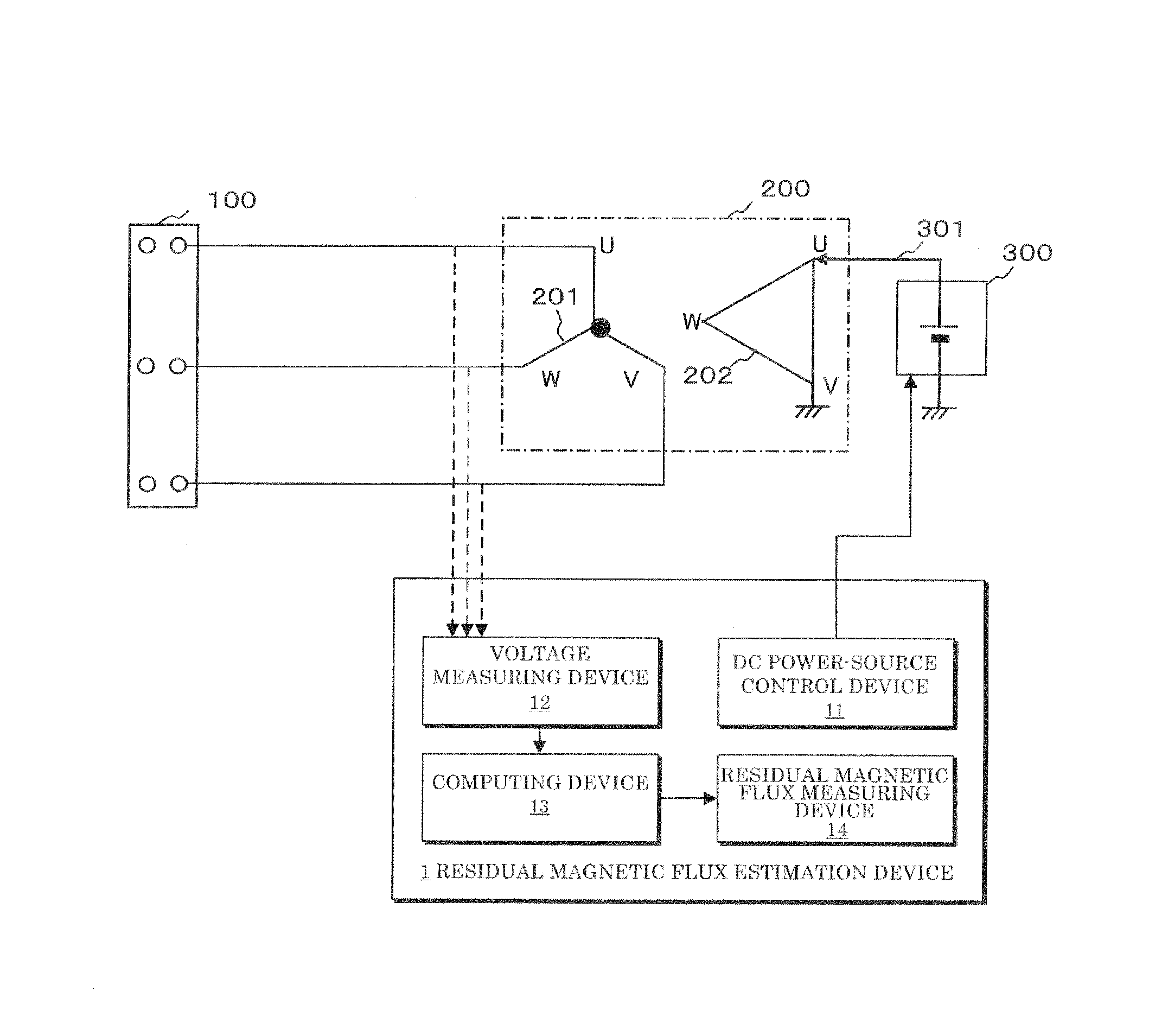
[0029]The structures and workings of a residual magnetic flux estimation device 1 of this embodiment, a breaker 100 allowing this device 1 to perform a residual magnetic flux estimating method, and the structures and workings of a transformer 200 and a DC power source 300 will be explained below.

1-1. Structure

[0030]In FIG. 1, reference numeral 100 indicates a three-phase breaker, reference numeral 200 indicates a three-phase transformer that is loaded to or cut off from a power-source bus by the thre...

second embodiment

2. Second Embodiment

[0049]In a second embodiment, when no voltage measuring unit is installed at the primary side of the transformer 200, by measuring the terminal voltage at the secondary or the tertiary Δ-connection side, a primary-side terminal voltage is obtained. Other structures of the second embodiment are basically in common with those of the first embodiment illustrated in FIG. 1.

[0050]More specifically, as illustrated in FIG. 4, a residual magnetic flux estimation device 2 of the second embodiment employs the following structures.

[0051](1) A DC power-source control device 21 which controls the DC power source 300 and which applies a DC voltage across the two terminals of the Δ connection that is the secondary or tertiary winding.

[0052](2) A voltage measuring device 22 that measures a terminal voltage of each terminal of the Δ connection of the three-phase transformer 200.

[0053](3) A computing device 23 which computes a phase-to-phase voltage by subtracting each terminal vo...

third embodiment

3. Third Embodiment

[0060]The basic structure of the residual magnetic flux estimation device of a third embodiment is basically consistent with that of the first embodiment. According to the third embodiment, a device that performs the following calculation in addition to the function of the first embodiment as the computing device 13 is used.

[0061](1) Determine whether the phase-to-phase voltages of the two phases other than the terminal voltages at the primary side or the voltage-applied phase at the h-connection side are equal or not.

[0062](2) When the voltages of the two phases are equal, determine phase-to-phase voltage between the voltage applied phase and the next phase in a vector representation or phase-to-phase voltage between the voltage applied phase and the previous phase in the vector representation.

[0063]Moreover, the residual magnetic flux measuring device 14 measures a phase-to-phase residual magnetic flux of each phase, and the computing device 13 estimates a phase...


PUM


Abstract

A residual magnetic flux estimation device 1 includes a DC power-source control device 11 which controls a DC power source 300 to apply a DC voltage across two terminals of a Δ connection that is a secondary winding or a tertiary winding, a voltage measuring device 12 which measures a terminal voltage at the primary side of a three-phase transformer 200, a computing device 13 that determines a phase having a high voltage between the two phases other than the phase to which the voltage is applied, and a residual magnetic flux measuring device 14 that measures a phase-to-phase residual magnetic flux between the two phases other than the high-voltage phase, and estimates a measured value of the phase-to-phase residual magnetic flux as a maximum residual magnetic flux in the measurement-target three-phase transformer.

Description

TECHNICAL FIELD[0001]The embodiments described herein relate to a method of estimating the residual magnetic flux of a transformer and a residual magnetic flux estimation device.BACKGROUND ART[0002]When a transformer core is subjected to a no-load excitation with magnetic fluxes remained through a power-on, a large excitation inrush current flows depending on a loaded phase. It is commonly known that the magnitude of this excitation inrush current becomes several times as much as a rated load current of the transformer. When such a large excitation inrush current flows, the system voltage fluctuates. This may affect a user when the voltage fluctuation is large.[0003]Conventionally, the following various methods for suppressing the excitation inrush current are known.[0004](1) Connect a breaker with a resistor having the loaded resistor and a contact connected in series to a breaker main contact in parallel to load the breaker with the resistor prior to the breaker main contact.[0005...

Claims


Application Information

Patent Timeline
Patent Type & Authority Applications(United States)
IPC IPC(8): G01R33/02
CPCG01R33/0064G01R33/02G01R33/12
Inventor UDAGAWA, KEISUKEKOSHIZUKA, TADASHISAITOH, MINORUSATO, YOSHIMASAMAEHARA, HIROYUKI
Owner KK TOSHIBA
Why Eureka
Try Eureka