
Electoactive polymer actuator

a polymer actuator and actuator technology, applied in piezoelectric/electrostrictive/magnetostrictive devices, instruments, optics, etc., can solve the problems of inability to adjust the position of the actuator, and inability to produce sharp edges, etc., to reduce the energy consumption of the life cycle, reduce the local stress, and reduce the effect of energy consumption

Inactive Publication Date: 2013-07-11
SIGNIFY HLDG BV
View PDF20 Cites 15 Cited by
  • Summary
  • Abstract
  • Description
  • Claims
  • Application Information

AI Technical Summary

Benefits of technology

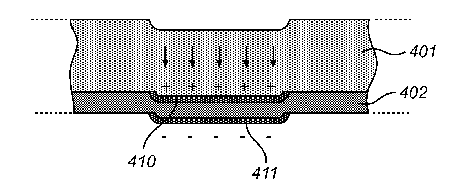
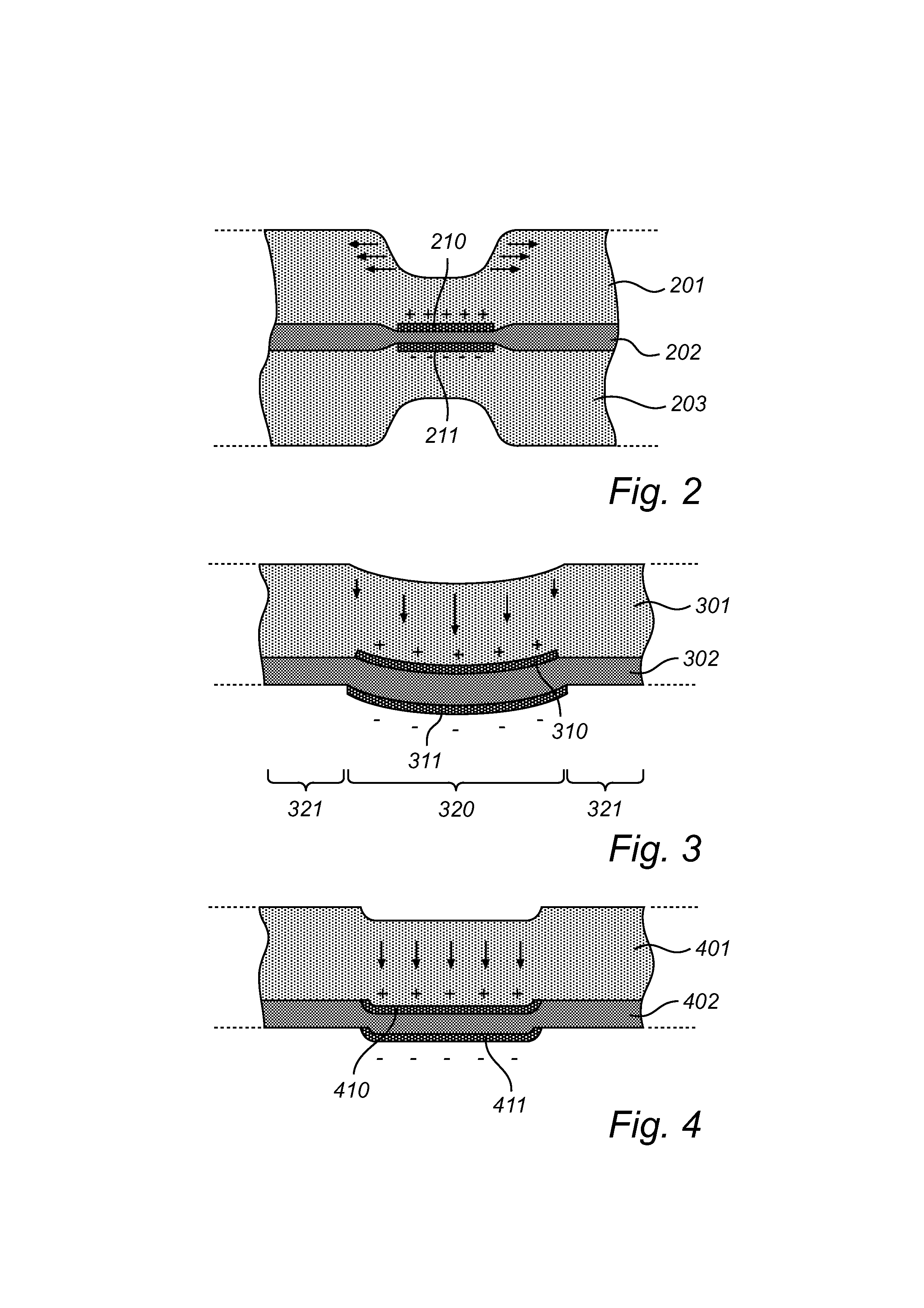
The invention is a new type of actuator that can create texture and enhance the sense of touch with a small amount of energy expense. It achieves this by using a thicker layer of material that is deformed into a smaller shape when the actuator is activated. This results in a significant vertical amplitude, or deep topography, at a lower energy cost compared to other types of actuators. The actuator can create texture-enhancing edges by shifting a bounded region out-of-plane in a single direction. It also eliminates the need for pre-strained actuator films and allows for greater freedom in the design of the electrodes. The actuator can be manufactured by separate sub-laminates that are laminated together. This method improves efficiency, especially if one of the sub-laminates includes a plurality of bonded layers, a temperature-treated or radiation-treated constituent, or a pre-stretched layer. The actuator can deform in duck mode as desired and is designed to avoid bending deflections.

Problems solved by technology

The material making up the elevated edge is supplied from the active area by stretching the latter into a thinner shape; such stretching may not be acceptable in all applications.
While actuators of this type may achieve a relatively large deflection amplitude, they are generally unable to produce sharp edges, hence not ideal for tactile applications.
Further, it has turned out that buckling-mode actuators perform best for symmetric shapes, such as square-shaped or round shapes, and will therefore not be compatible with too irregular electrode shapes.

Method used


Image

  • Electoactive polymer actuator
  • Electoactive polymer actuator
  • Electoactive polymer actuator

Examples


example

[0048]Without being limited thereto, the invention will be illustrated by an example concerning an actuator of the type shown in FIG. 5.

[0049]First, an 80 μm thick film of Nusil® CF 2186 was fabricated using for instance doctor blading of the freshly mixed components onto an anti-adhesive plate, such as a Teflon® plate. This layer, which would form the EAP layer of the laminate, was cured at 60° C. for one hour. Next, a stretchable electrode was made on top of the Nusil® layer by screen printing carbon black (e.g., Monarch® 1000) in n-heptane through a patterned screen. Subsequently, a thicker, softer polymer (e.g., Silastic®) was casted or doctor-bladed over the EAP layer and electrode. After polymerization (in air, for Silastic®), this formed a passive layer acting as texture enhancement layer with a lower elastic modulus than the actuation layer: Silastic® has a modulus of about 0.3 MPa, while Nusil® has a modulus of about 1 MPa. For tactile applications, the thickness of this la...


PUM


Abstract

An actuator comprises an electroactive polymer layer (402) and stretchable electrode structures (410, 411) that are disposed on each side of the electroactive polymer layer (402). A softer passive layer (401) is secured to one of the stretchable electrode structures (410, 411). When compressed transversally by the stretchable electrode structures (410, 411), the electroactive polymer layer (402) will expand tangentially and the actuator will relax into a shape wherein the interior of the electroded region is substantially parallel to the plane of the device, while a substantial portion of the area increase is absorbed by out-of-plane bends arising at the electrode boundary (duck mode). The invention can be embodied as optically reflective or refractive devices with variable geometry.

Description

FIELD OF THE INVENTION[0001]The invention disclosed herein generally relates to electroactive polymer actuators. In particular, it relates to an actuator with an asymmetric layered structure allowing localized out-of-place actuation.[0002]The invention also relates to a method of manufacturing such an actuator.BACKGROUND OF THE INVENTION[0003]Dielectric actuators in the form of laminates (or sandwich structures or layered materials) belong to a rapidly evolving field of technology. A simple dielectric actuator may comprise a layer of electroactive polymer and an electrode pair for applying an electrostatic force and thereby causing an elastic deformation of the polymer layer in the tangential and / or transversal direction. More sophisticated dielectric actuators may include functional additional layers, such as optically reflective or antireflective layers, texture-enhancing layers, electrically and / or thermally conductive layers, etc.[0004]The way in which a dielectric actuator resp...

Claims


Application Information

Patent Timeline
IPC IPC(8): G02B26/08
CPCG02B3/08G02B26/0825G02B26/0875G02B26/08H01L41/0973H01L41/0986G02B27/58H10N30/878H10N30/206H10N30/857
Inventor BROKKEN, DIRKCROMPVOETS, FLORIS MARIA HERMANSZDE KONING, HENDRIKMARTAM, WENDY MIREILLEVOSSEN, FRANCISCUS JACOBUSLIEDENBAUM, COEN THEODORUS HUBERTUS FRANSISCUS
Owner SIGNIFY HLDG BV
Learn More