
Reactive energy compensator and associated method for balancing half-bus voltages

a technology of reactive energy and compensator, which is applied in the direction of electrical equipment, power conversion systems, ac network circuit arrangements, etc., can solve the problems of imbalance being able to vary, deteriorating the performance of reactive energy, and affecting the balancing speed of the reactive energy, so as to achieve the effect of increasing the balancing speed

Active Publication Date: 2013-07-11
GE ENERGY POWER CONVERSION TECH
View PDF4 Cites 12 Cited by
  • Summary
  • Abstract
  • Description
  • Claims
  • Application Information

AI Technical Summary

Benefits of technology

The invention is a device that helps to balance the electricity in a network. It uses a special compensator to add a balancing current to the control current, which reduces the difference between the two voltages. This results in faster balancing between the two voltages. Overall, the invention improves the stability and efficiency of electrical networks.

Problems solved by technology

In such an electrical network, certain disruptions, such as disruptions following the connection of an arc furnace on the network for example, can nevertheless cause an imbalance in the values of the first and second voltages of the or each inverter, that imbalance being able to vary from one inverter to the next.
The existence of such an imbalance deteriorates the performance of the reactive energy compensator and may lead to the deactivation thereof if the value of the imbalance exceeds a certain threshold.
Nevertheless, such a conversion device cannot be used as is in a reactive energy compensator of the aforementioned type to resolve the problem of rebalancing the values of the first and second voltages of the or each inverter.
In fact, the transient states due to the electrical disruptions are stronger in a reactive energy compensator than a power supply system, and that solution is not satisfactory in particular in terms of the speed of correction used.

Method used


Image

  • Reactive energy compensator and associated method for balancing half-bus voltages
  • Reactive energy compensator and associated method for balancing half-bus voltages
  • Reactive energy compensator and associated method for balancing half-bus voltages

Examples


Embodiment Construction

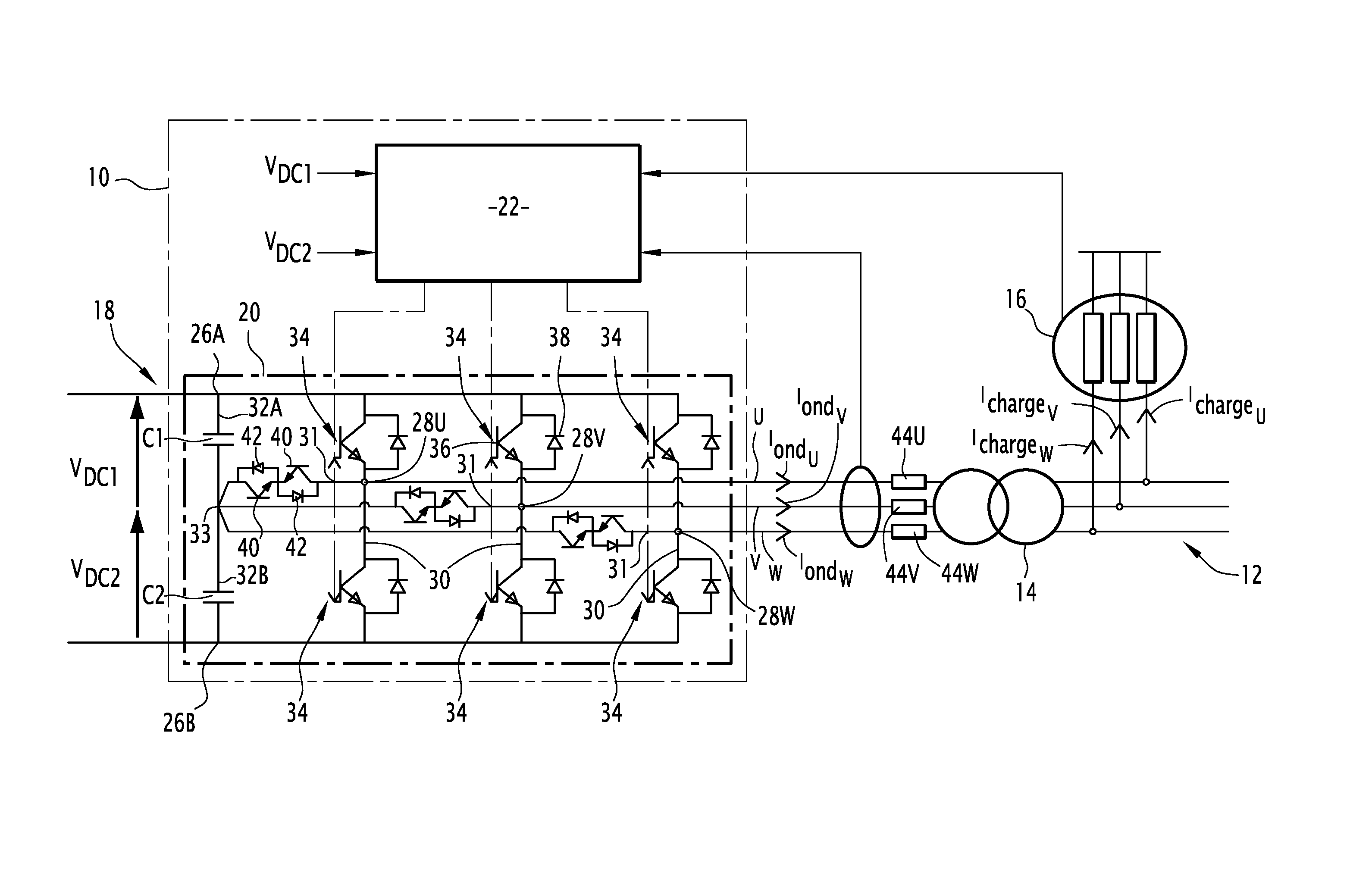
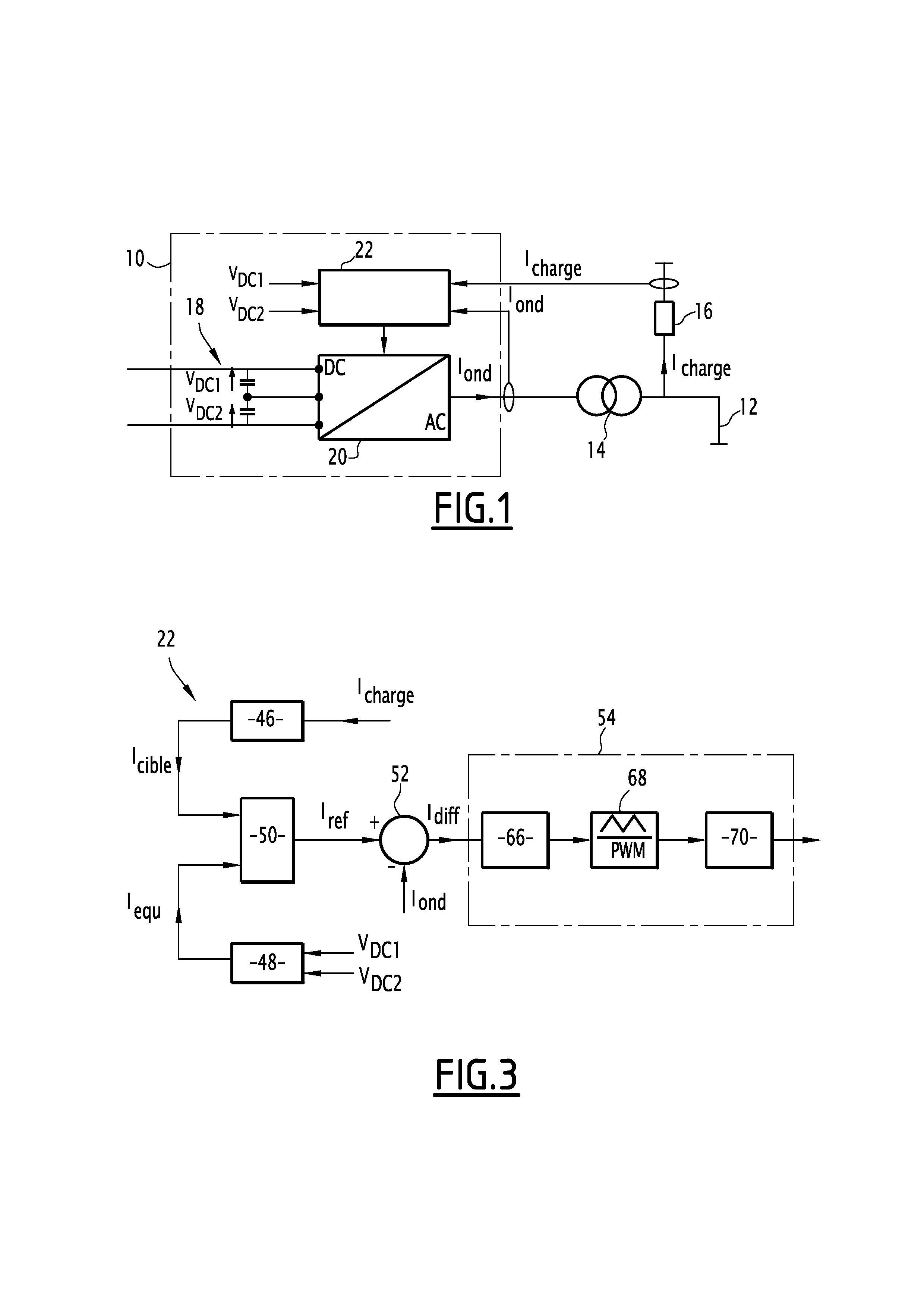
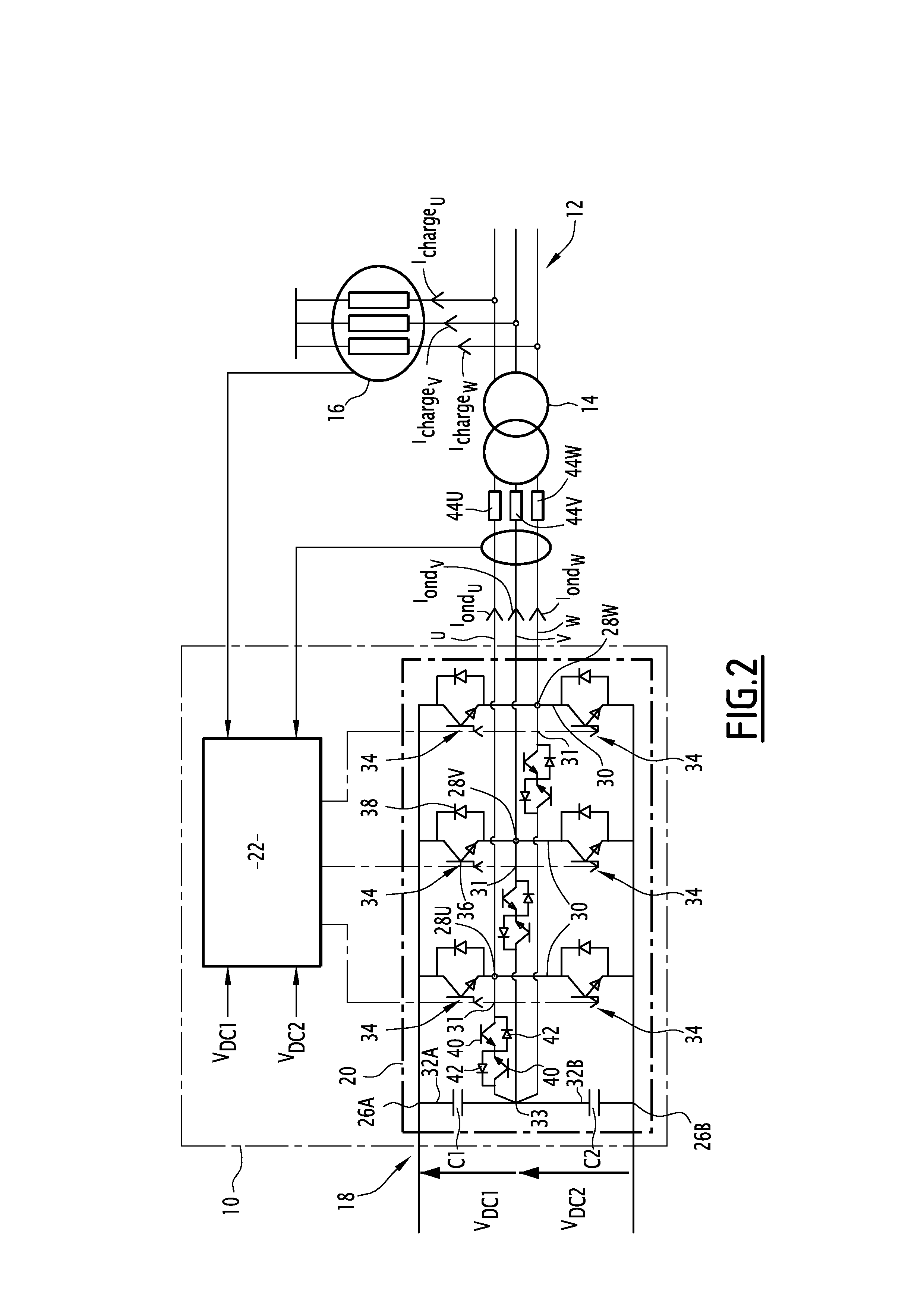
[0037]FIG. 1 shows a system 10 for converting a direct input current into a polyphase alternating output current. The conversion system 10 is connected on the one hand to a direct or rectified current source, not shown, and on the other hand to an electrical network 12, by means of a voltage transformer 14.

[0038]The electrical network 12 is, for example, a high-voltage three-phase alternating network, typically in the vicinity of 33 kV between phases and with a frequency f1 for example equal to 50 Hz. An arc furnace 16 is also connected to the electrical network 12.

[0039]The conversion system 10 includes a direct voltage bus 18 and a voltage inverter 20, capable of converting a direct input current into a polyphase alternating output current. This inverter is connected to the direct or rectified current source by means of the direct voltage bus 18.

[0040]The current Iond shown in FIG. 1 identifies an alternating current supplied as output from the inverter 20 for any phase.

[0041]The ...


PUM


Abstract

A reactive energy compensator that can be electrically connected to an AC electrical network, including at least one input direct voltage bus, at least one voltage inverter including switches and first and second capacitors having first and second voltages at their terminals, control means for the switches, including computation means capable of generating a target control current, means for combining the target control current and the output current from the inverter, means for transmitting a control signal capable of driving the switches, and correction means for the control signals of the switches, the correction means being capable of adding a balancing current to the target control current, the balancing current being able to correct the target control current so as to reduce the difference between the values of the first and second voltages, the target control current being increased for an even harmonic of the network frequency.

Description

CROSS REFERENCES TO RELATED APPLICATIONS[0001]This application claims foreign priority benefit of French Patent Application No. 12 50196, entitled COMPENSATEUR D'ÈNERGIE RÈACTIVE ET PROCÈDÈ D'EQUILIBRAGE DE TENSIONS DE DEMI-BUS ASSOCIÈ, filed on Jan. 9, 2012.FIELD OF THE INVENTION[0002]The field of the present invention is reactive energy compensators.BACKGROUND OF THE INVENTION[0003]The present invention relates to a reactive energy compensator capable of being electrically connected to an AC electrical network having M phase(s) and having a network frequency, M being greater than or equal to 1, the compensator comprising M phase(s) and including:[0004]at least one input direct voltage bus capable of supplying reactive energy,[0005]at least one voltage inverter connected to the direct voltage bus and capable of converting a direct input current into an alternating output current, the or each inverter comprising two input terminals, M output terminal(s) and M switching branches, eac...

Claims


Application Information

Patent Timeline
Patent Type & Authority Applications(United States)
IPC IPC(8): H02M7/537
CPCH02J3/1857H02M7/537Y02E40/26H02M7/487Y02E40/22H02J3/1842Y02E40/20
Inventor MORATI, MATHIEUURBAIN, MATTHIEUGIROD, DANIEL
Owner GE ENERGY POWER CONVERSION TECH
Learn More