System and method for monitoring in real time the operating state of an IGBT device

a technology of igbt and junction temperature, which is applied in the field of system and method for measuring or estimating the junction temperature of an igbt device, can solve the problems of inability to provide timely resolution and precision in the method of determining the temperature, and the technique is not suitable for online measurement of the igbt junction temperatur

Active Publication Date: 2013-07-11
ABB (SCHWEIZ) AG
View PDF1 Cites 36 Cited by
  • Summary
  • Abstract
  • Description
  • Claims
  • Application Information

AI Technical Summary

Problems solved by technology

Due to the delayed thermal response when the temperature is not measured directly at the semiconductor junction, the above methods for determining the temperature do not provide the required timely resolution and preci...

Method used


Image

  • System and method for monitoring in real time the operating state of an IGBT device
  • System and method for monitoring in real time the operating state of an IGBT device
  • System and method for monitoring in real time the operating state of an IGBT device

Examples


Embodiment Construction

[0016]Exemplary embodiments of the present disclosure provide a system and a method for determining a junction temperature of an IGBT device that provides an indication of the temperature with high precision and in high timely resolution.

[0017]Exemplary embodiments of the present disclosure provide a system and a method for determining at least one of a junction temperature and a remaining lifetime of an IGBT device.

[0018]Additional features of the present disclosure are explained in more detail below with reference to exemplary embodiments illustrated in the drawings.

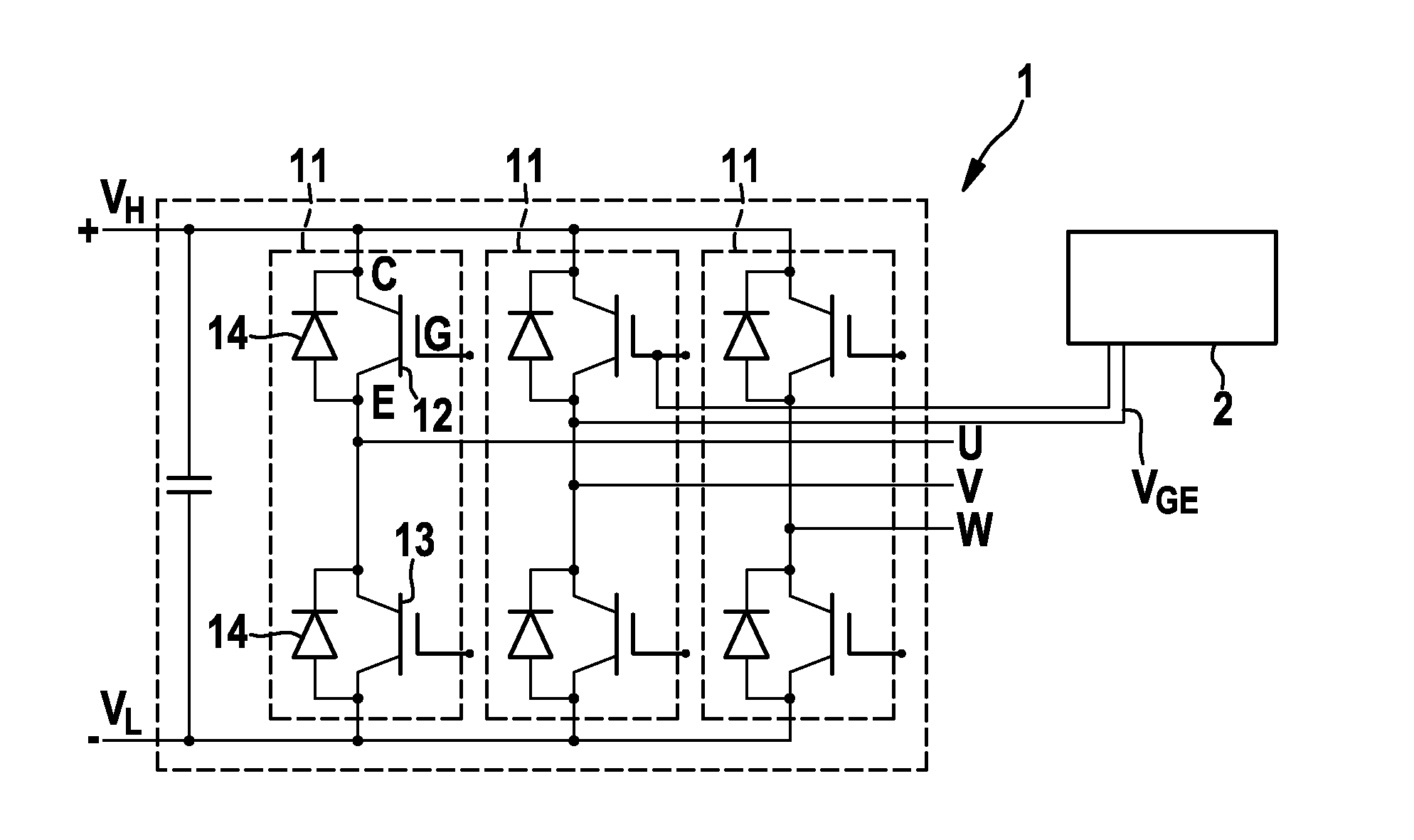
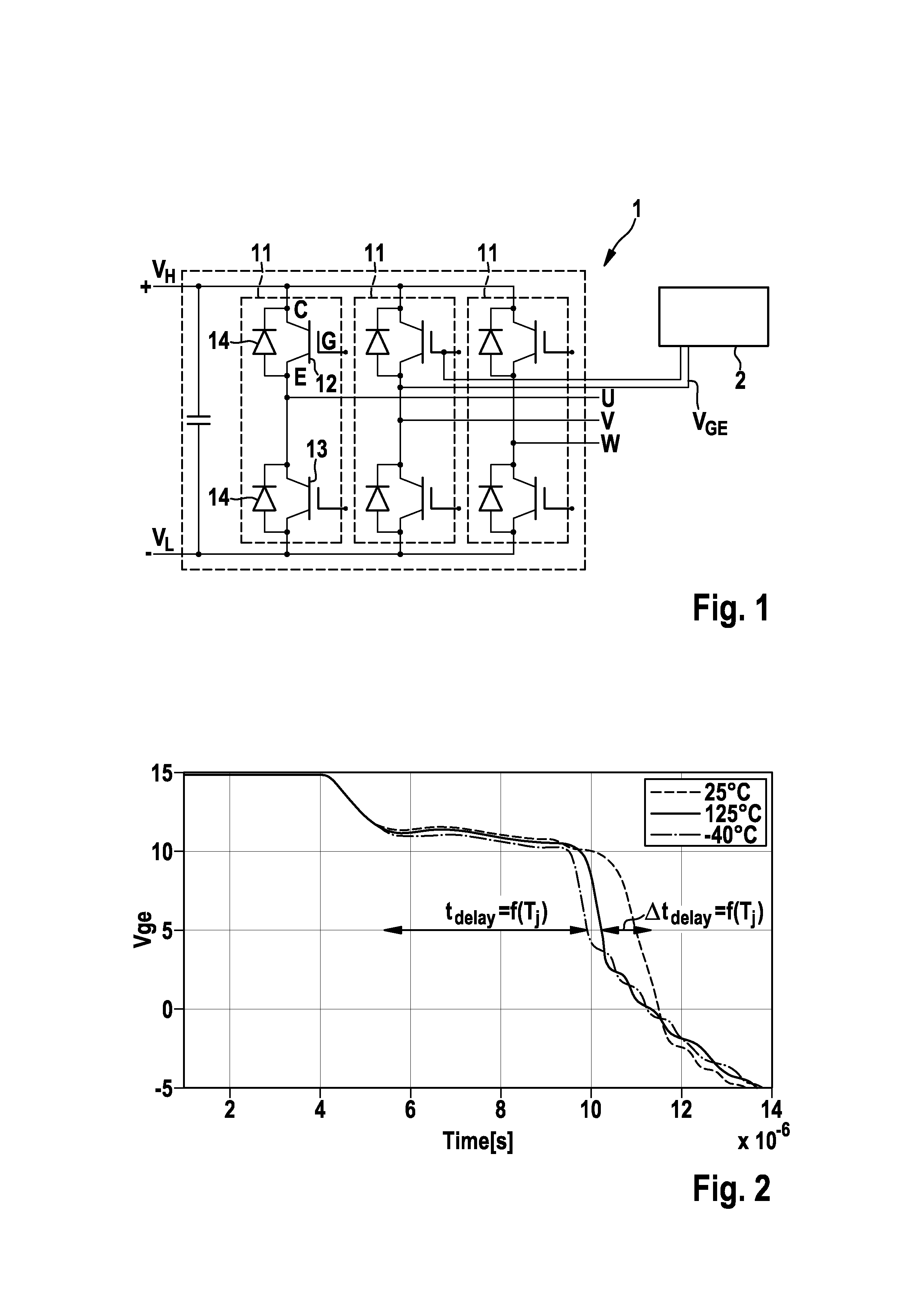
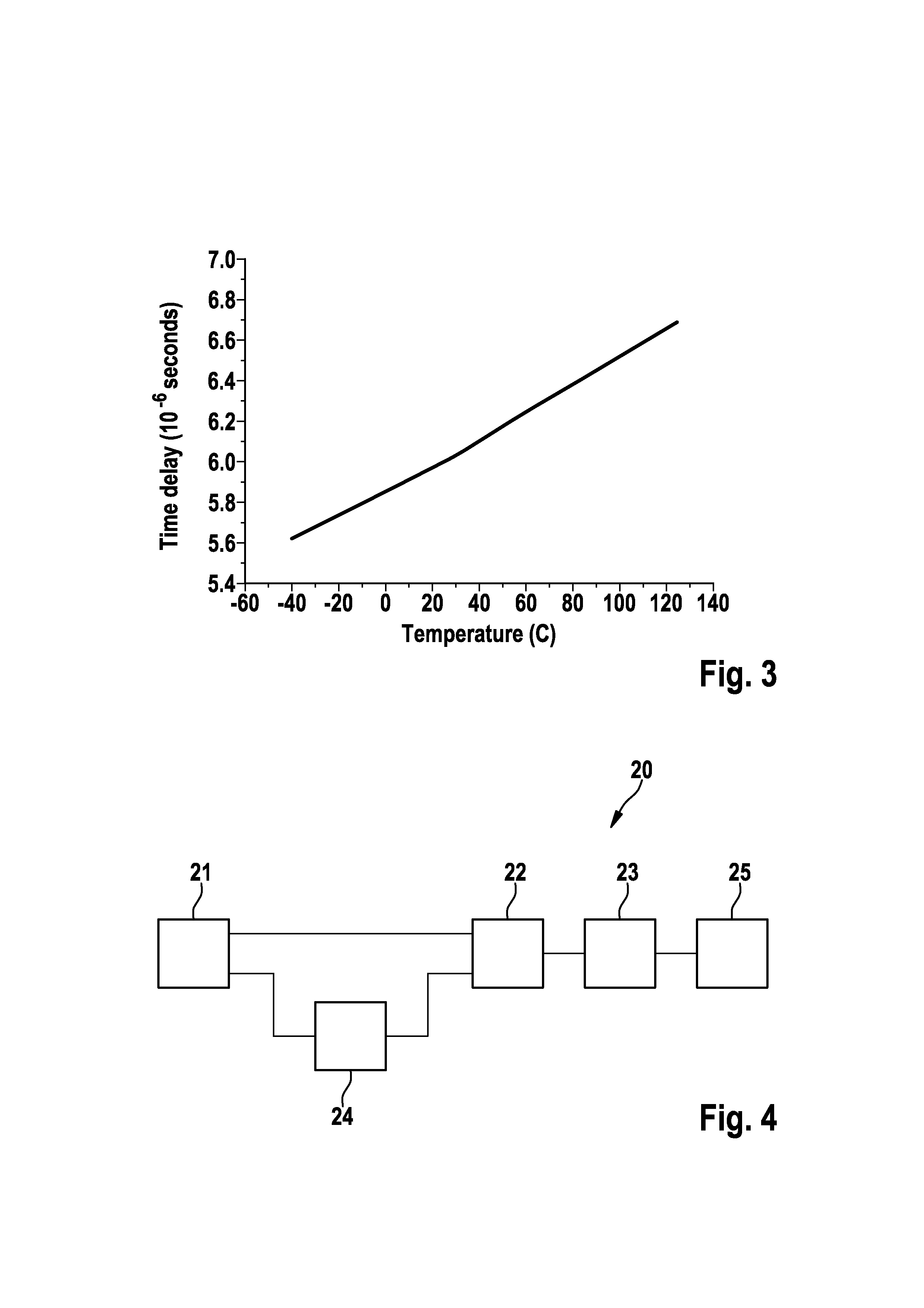
[0019]An exemplary embodiment of the present disclosure provides a system for determining at least one of a junction temperature and a remaining lifetime of an IGBT device. The system includes a differential unit configured to receive a gate-emitter voltage characteristic of the IGBT device to be measured and to differentiate the gate-emitter voltage characteristic to obtain pulses correlating with edges formed by a Mi...


PUM


Abstract

A system and method are provided for monitoring in real time the operating state of an IGBT device, to determine a junction temperature and/or the remaining lifetime of an IGBT device. The system includes a differential unit configured to receive a gate-emitter voltage characteristic of the IGBT device to be measured and to differentiate the gate-emitter voltage characteristic to obtain pulses correlating with edges formed by a Miller plateau phase during a switch-off phase of the IGBT device. The system also includes a timer unit configured to measure the time delay between the obtained pulses indicating the start and end of the Miller plateau phase during the switch-off phase of the IGBT device, and a junction temperature calculation unit configured to determine at least one of the junction temperature of the IGBT device and/or the remaining lifetime of the IGBT device based on the measured time delay.

Description

RELATED APPLICATION[0001]This application claims priority under 35 U.S.C. §119 to European Patent Application No. 12150704.0 filed in Europe on Jan. 11, 2012, the entire content of which is hereby incorporated by reference in its entirety.FIELD[0002]The present disclosure relates to the field of insulated gate bipolar transistor (IGBT) devices. More particularly, the present disclosure relates to a system and method for measuring or estimating a junction temperature of an IGBT device.BACKGROUND INFORMATION[0003]The junction temperature of IGBT devices in semiconductor modules during operation in, for example, a power electronic converter, is an important parameter that provides information about the thermal stress the device is exposed to. Hence, it can be used to predict and evaluate the ageing of the IGBT device as well as the power module and to estimate the remaining lifetime of the IGBT device.[0004]It is known for the junction temperature of an IGBT device to be measured using...

Claims


Application Information

Patent Timeline
IPC IPC(8): H01L21/66G01K7/01
CPCG01R31/2619H01L22/30G01K7/01H03K2017/0806H03K17/18G01K2217/00G01R31/2642G01R31/26
Inventor SUNDARAMOORTHY, VINOTHHEINEMANN, ALEXANDERBIANDA, ENEAZURFLUH, FRANZKNAPP, GEROLDNISTOR, IULIANBLOCH, RICHARD
Owner ABB (SCHWEIZ) AG
Why Eureka
Try Eureka