Method for Controlling a Headlamp System for a Vehicle, and Headlamp System

a headlamp system and vehicle technology, applied in the direction of lighting and heating equipment, instruments, transportation and packaging, etc., can solve the problems of reducing the efficiency of the headlamp system, and reducing the delay time. , to achieve the effect of rapid assignmen

Active Publication Date: 2013-07-11
VOLKSWAGEN AG
View PDF5 Cites 22 Cited by
  • Summary
  • Abstract
  • Description
  • Claims
  • Application Information

AI Technical Summary

Benefits of technology

[0083]An advantage of determining the temporal coherence of the confidence values is that the difficult tracking of a region within an image sequence is dispensed with. To arrive at a reliable assignment of the regions to vehicle lights, it is sufficient to consider the accumulation field for only very few full images, so that a very rapid assignment is possible.
[0084]According to example embodiments of the present invention, the traffic region in a horizontal opening angle of more than 40° is recorded. The advantage of using such an opening angle is that the image may be employed not only for detecting vehicles when it is dark, but that it may also be utili...

Problems solved by technology

When the visual conditions are poor, especially in the dark, it is the task of the headlamps of a vehicle to illuminate the environment in front of the vehicle in the driving direction, in particular the roadway.
However, it has the disadvantage of blinding other road users, in particular the drivers of vehicles driving ahead and of vehicles approaching from the opposite direction.
However, in contrast to the masked permanent high beam, no vertical light-dark cutoff in the center of the total light pattern is produced in the sliding illumination range.
In particular, the more frequently additional road users are detected, especially oncoming road users, the greater the delay time.
In contrast, at high speeds as they are typically encountered on an expressway, a newly detected additional r...

Method used


Image

  • Method for Controlling a Headlamp System for a Vehicle, and Headlamp System
  • Method for Controlling a Headlamp System for a Vehicle, and Headlamp System
  • Method for Controlling a Headlamp System for a Vehicle, and Headlamp System

Examples


Embodiment Construction

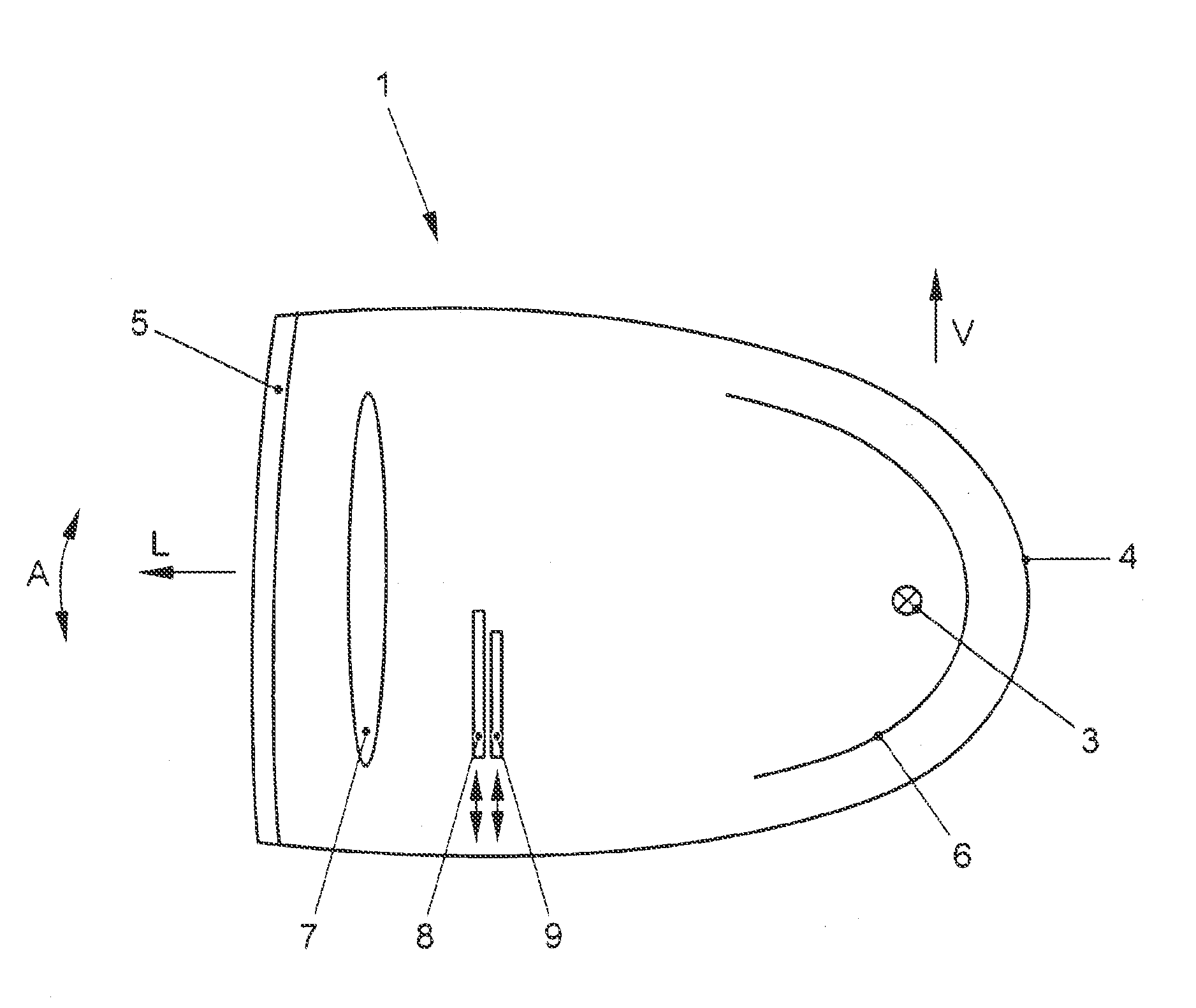
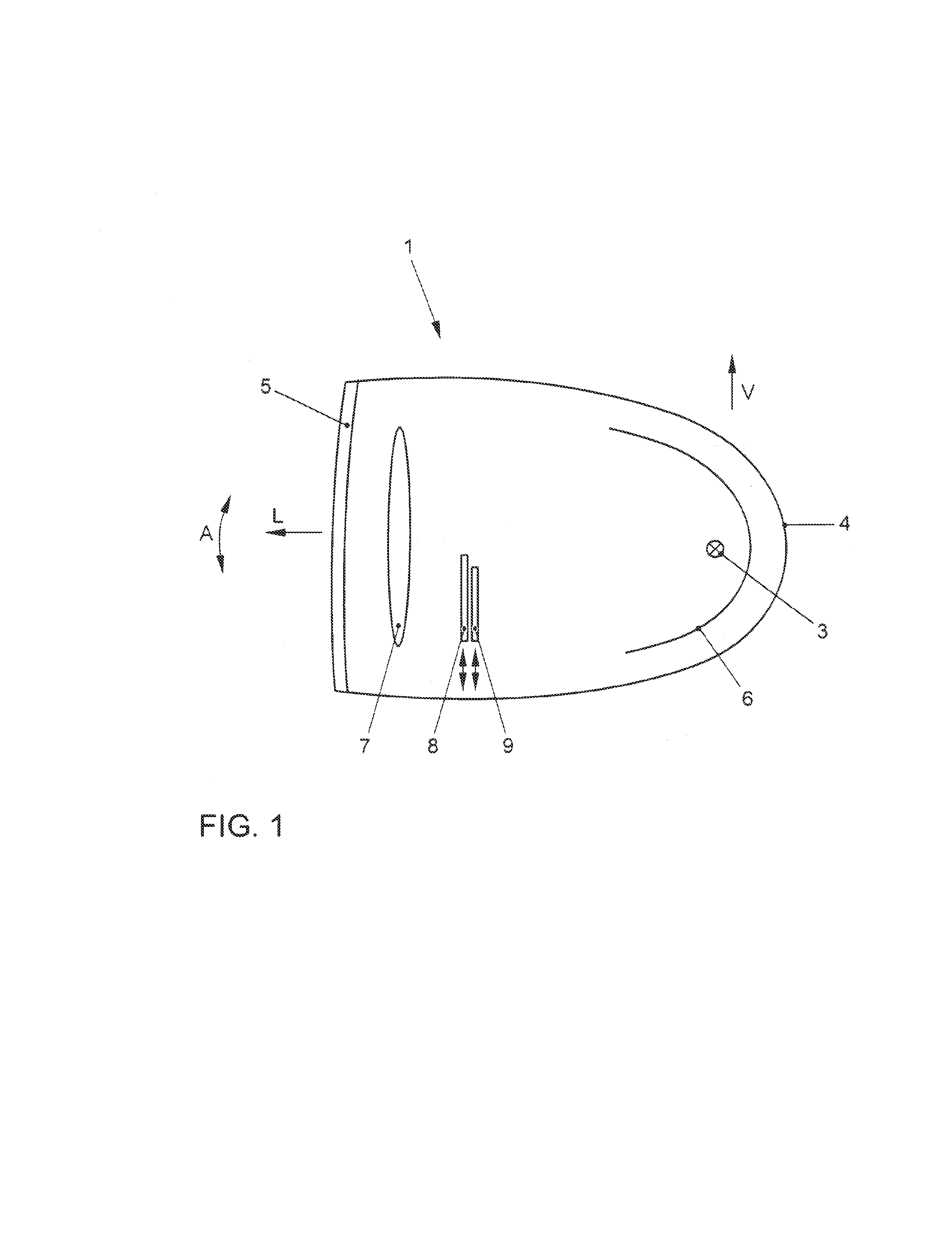
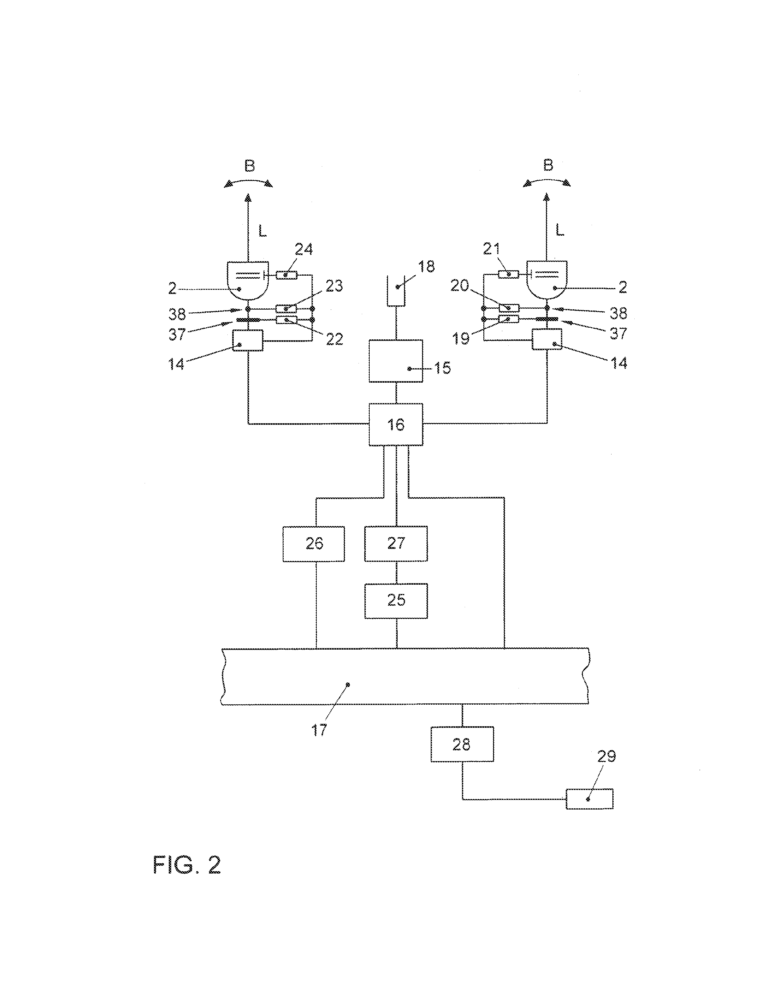
[0109]The headlamp system, which is shown in schematic form in FIG. 2, includes two projection headlamps 1 and 2 which are set apart from each other and situated in the front on the right and left side of the vehicle, e.g., in a conventional manner. One of these projection headlamps 1, 2 is shown in FIG. 1. Projection headlamp 2 situated on the other side has substantially the same design.

[0110]FIG. 1 shows a section of projection headlamp 1 in a plane that is parallel to the plane defined by the longitudinal vehicle axis and vertical V. In the conventional manner, projection headlamp 1 includes a light source 3, which is surrounded by a reflector 6 implemented as rotation ellipsoid. Reflector 6 thus has two focal points. Light source 3 is located in one of the focal points of reflector 6. The light emitted by light source 3 is reflected by reflector 6 in light emission direction L of projection headlamp 1, in the direction of a projection lens 7. A diaphragm array having planar dia...


PUM


Abstract

In a method for controlling a headlamp system for a vehicle, the headlamp system having two headlamps, set apart from each other, road users are detected in front of the vehicle in the driving direction, and a first total light pattern is able to be produced, in which the illumination range on a first side of a center axis is greater than on the other, second side of this center axis, and a second total light pattern is able to be produced, in which the total light pattern is controllable such that it has an illumination range in the direction of at least one detected road user that is less than the distance to the detected road user, and which has an illumination range in another direction that is greater than the distance to the detected road user. During the switch from the first total light pattern to the second total light pattern, the illumination range of at least one headlamp on the first side of the center axis is first reduced to at least such an extent that it is less than the distance to the detected road user, the second total light pattern being produced subsequently.

Description

FIELD OF THE INVENTION[0001]The present invention relates to a method for controlling a headlamp system for a vehicle; it also relates to a headlamp system for a vehicle equipped with a control device.BACKGROUND INFORMATION[0002]When the visual conditions are poor, especially in the dark, it is the task of the headlamps of a vehicle to illuminate the environment in front of the vehicle in the driving direction, in particular the roadway. In addition, the headlamps serve to identify the vehicle to other road users.[0003]For the light emission in the driving direction, it is conventional to provide headlamps which are able to offer a low beam functionality and a high beam functionality. The high beam functionality produces a very comprehensive illumination of the environment. However, it has the disadvantage of blinding other road users, in particular the drivers of vehicles driving ahead and of vehicles approaching from the opposite direction. The low beam, on the other hand, makes i...

Claims


Application Information

Patent Timeline
IPC IPC(8): B60Q1/08G06K9/00
CPCB60Q1/143B60Q1/085B60Q2300/112B60Q2300/114B60Q2300/122B60Q2300/20B60Q2300/322B60Q2300/335B60Q2300/338B60Q2300/41B60Q2300/42G06K9/00825G06K9/3241G06K2209/23B60Q1/08G06K9/00624B60Q2300/056G06V20/584G06V10/255G06V2201/08B60Q1/14G06F18/00B60Q1/16
Inventor DIERKS, KARSTENFREESE, MARTINJAHRSAU, BERND
Owner VOLKSWAGEN AG
Why Eureka
Try Eureka