
Abrading arrangement to abrade a surface of an item and method of use thereof

Inactive Publication Date: 2013-07-11
ELTRONIC
View PDF0 Cites 23 Cited by
  • Summary
  • Abstract
  • Description
  • Claims
  • Application Information

AI Technical Summary

Benefits of technology

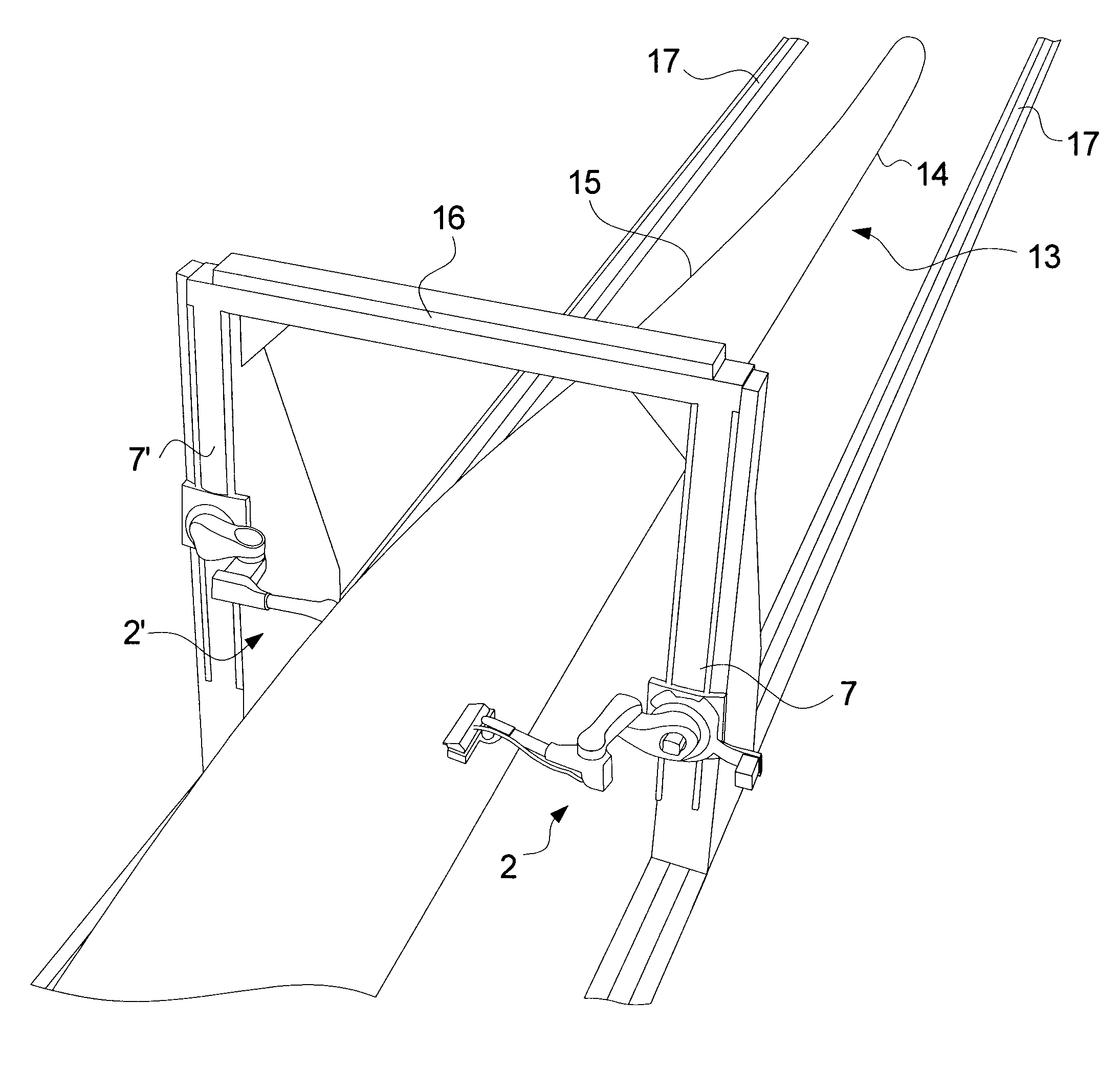
The present invention relates to an abrasion arrangement for wind turbine blades. The arrangement includes a robotic arm with at least 5 degrees of freedom that can move the abrading cylinder across the surface of the blades in different directions to achieve uniform abrasion. The arm has the ability to adjust to complex surfaces and can handle areas around edges without damaging the abrasive lamellae or causing damage to the blades. The arrangement includes sensors to detect the actual shape of the surface being abraded, which allows for precise control of the abrasion process. The technical effects of this invention include the production of wind turbine blades with consistent and predictable aerodynamic properties.

Problems solved by technology

However, the abrasion of the surface of larger items, where it is impractical to provide stationary abrasive means of dimensions sufficiently large is e.g. known to be provided by means of a robotic arm carrying abrasive means as disclosed in US 2002 / 0072297 for the surface treatment of panels for aircrafts and from the Spanish company EINA which in the magazine Wind Systems of March 2010 disclosed surface grinding of a wind turbine blade by means of a 8-axis robot handling e.g. a sanding head having a plurality of abrasive disks arranged.

Method used


Image

  • Abrading arrangement to abrade a surface of an item and method of use thereof
  • Abrading arrangement to abrade a surface of an item and method of use thereof
  • Abrading arrangement to abrade a surface of an item and method of use thereof

Examples


Embodiment Construction

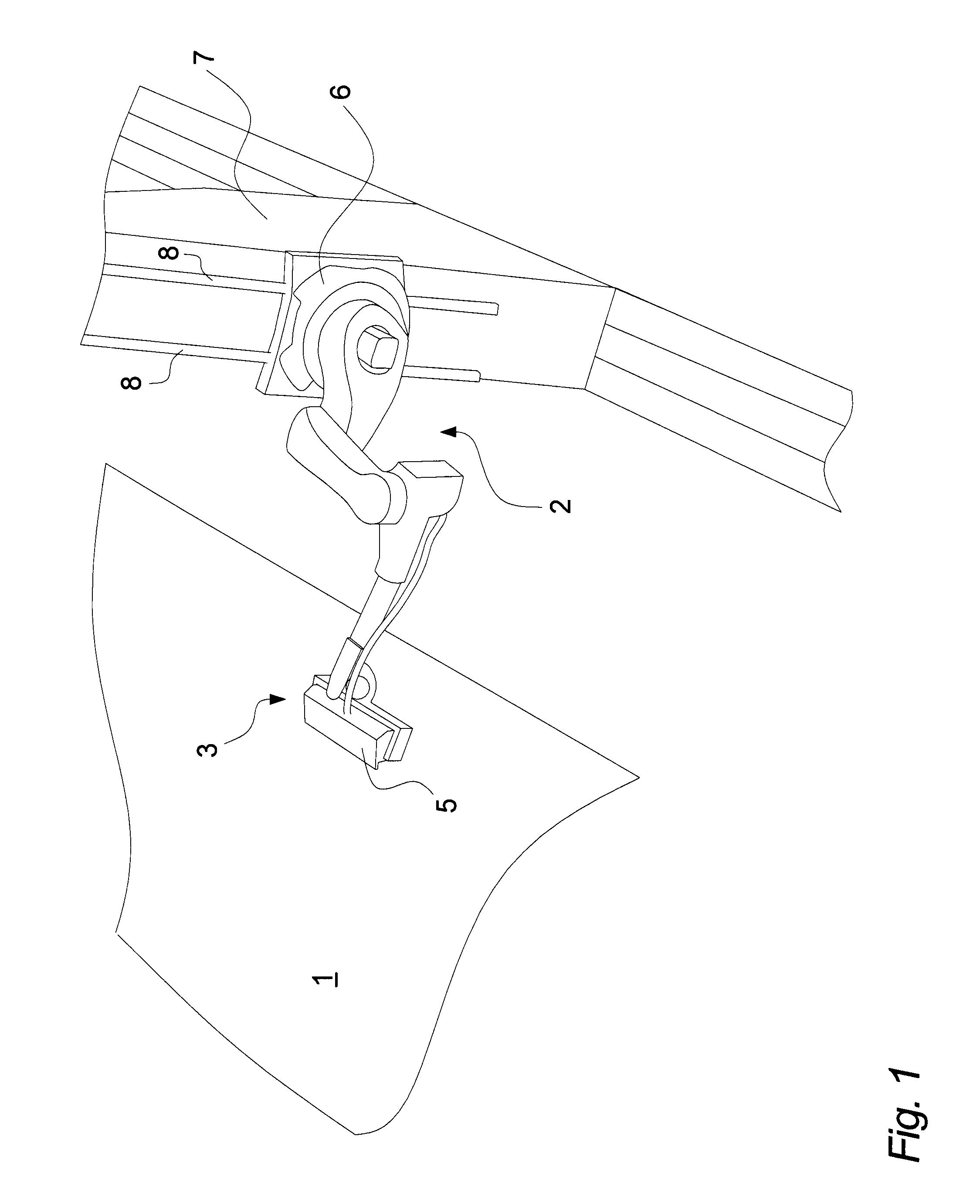
[0029]An abrasion arrangement of the present invention for abrading of a surface 1 is shown in FIG. 1 comprising a 6-axis articulated robotic arm 2 on which is mounted an abrasion head 3 having an abrading cylinder 4 enclosed in a shielding housing 5 provided with a suction outlet (not shown) for removal of dust and a motor (not shown) for driving the rotation of the abrading cylinder 4. The base 6 of the robotic arm 2 is in FIG. 1 mounted on a vertical column 7 equipped with parallel, vertical tracks 8 on which the base 6 is displaceable arranged in the vertical direction so as to enable abrasion of a surface 1 of a wider extent in the vertical direction than the robotic arm 2 itself allows for.

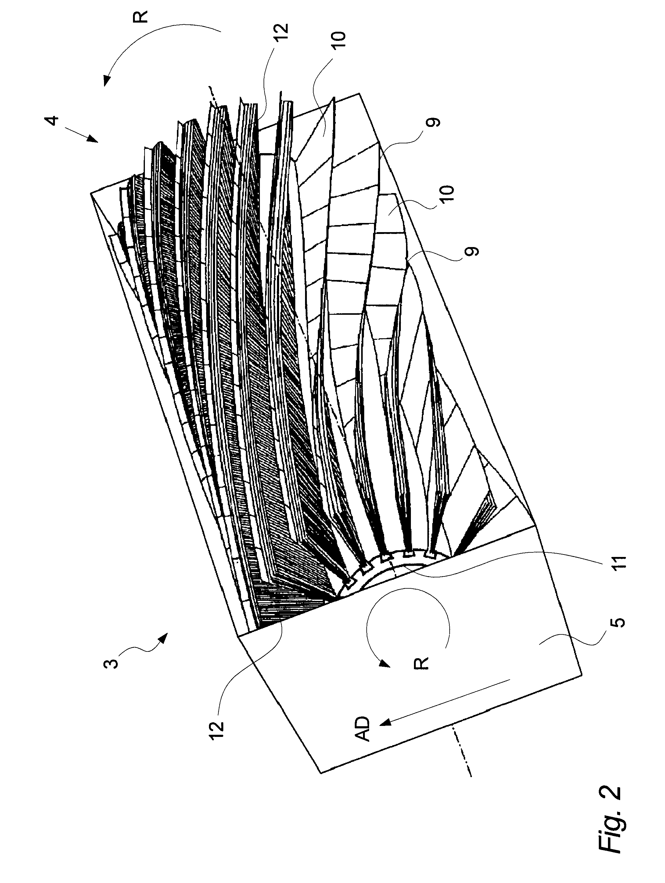
[0030]The abrading cylinder 4 shown in FIG. 2 has abrasive means which comprise abrasive lamellae 9 of an abrasive sheet, such as abrasive cloth, of which the front side 10 has abrasive properties and which extend substantially radially from an elongated core 11 of the cylinder. The abrasive...


PUM


Abstract

An abrasion arrangement is disclosed to abrade a surface of an item, the arrangement comprising a multiple axis robotic arm having at least five axes, an abrading cylinder mounted on the robotic arm and comprising abrasive means which comprise abrasive lamellae of an abrasive sheet, such as abrasive cloth, of which the front side has abrasive properties and which extend substantially radially from an elongated core and means for driving said core to rotate around a longitudinal axis of the core, and control means for controlling the operation of the robotic arm so to control e.g. the position of the abrading cylinder on said surface, the force with which the abrading cylinder is pressed towards said surface and the velocity with which the abrading cylinder is moved with respect to said surface.

Description

[0001]The present invention relates to an arrangement comprising a robotic arm carrying abrasive means for abrading the surface of an item and method of use of the arrangement.BACKGROUND[0002]Abrasion of the surface of items of a reasonable size by means of a stationary abrading machine is well-known in the art from e.g. WO 2004 / 098831. However, the abrasion of the surface of larger items, where it is impractical to provide stationary abrasive means of dimensions sufficiently large is e.g. known to be provided by means of a robotic arm carrying abrasive means as disclosed in US 2002 / 0072297 for the surface treatment of panels for aircrafts and from the Spanish company EINA which in the magazine Wind Systems of March 2010 disclosed surface grinding of a wind turbine blade by means of a 8-axis robot handling e.g. a sanding head having a plurality of abrasive disks arranged.[0003]However, improvements of the means for abrading the surface of large items in order e.g. to remove irregula...

Claims


Application Information

Patent Timeline
IPC IPC(8): B24B19/14B24B49/12
CPCB24B19/14B24B19/26B24B27/0038B24B29/00B25J11/0065B24B49/12B24D13/04B25J9/026B24B47/22
Inventor ERIKSEN, KELDLUNDUM, POUL
Owner ELTRONIC
Learn More