Tensioning Device with Damping Channel in the Fluid Supply System

a technology of fluid supply system and tensioning device, which is applied in the direction of mechanical equipment, belts/chains/gearrings, etc., can solve the problems of air accumulation in the pressure reservoir, hydrostatic fluid can incrementally escape, air can negatively affect the function of the tensioning device, etc., and achieves the effect of influencing the damping properties of the damping device, reducing the risk of slipping, and reducing the damping

Inactive Publication Date: 2013-07-11
IWIS MOTORSYSTEME GMBH & CO KG
View PDF2 Cites 9 Cited by
  • Summary
  • Abstract
  • Description
  • Claims
  • Application Information

AI Technical Summary

Benefits of technology

[0008]The venting device measures according to the invention must be differentiated. Said venting devices were specifically developed for the overhead installation of tensioning devices. For instance, EP 1602857 B1 reveals a tensioning device with a specially configured check valve housing that contains a choked bypass for venting into the oil supply channel. While such a configuration may also have an impact on the damping properties of the tensioning device, the supply of new hydraulic oil into the pressure reservoir is most likely exclusively provided via the open check valve due to the adjusted choke effect of the medium air. A similar venting design for overhead tensioning device installations is also disclosed by U.S. Pat. No. 5,643,117. According to this document, a special choke disc is used as a check valve mount. However, in both known designs, new hydraulic fluid is supplied primarily through the open check valve. No involvement of the venting design in this inflow is described. In contrast to these known designs, the invention also permits embodiments where the tensioning piston presses toward the top. In addition, in this known design, the exhausted air remains in the pressurized supply path, which can lead to problems.
[0009]In accordance with a preferred embodiment, the fluid supply can be equipped with a supply insert that is inserted into the housing with an accurate fit, where the at least one damping channel is arranged between the supply insert and the housing. By employing such an insert, the at least one damping channel can be easily created and also varied. This permits the use of simple methods to influence the damping properties of the damping device by employing a supply insert that matches the desired application.
[0010]The housing can be preferably configured with a receiving bore in which the tensioning piston can be located in a sliding manner, where the supply insert is seated with an accurate fit at the base of the receiving bore, and the at least one damping channel is arranged between the exterior surface of the supply insert and the interior surface of the receiving bore. This permits the supply insert to be conveniently inserted into the receiving bore from the front before the tensioning piston is inserted into the housing. The insertion with an accurate fit permits the easy attainment of a suitably sealed damping channel. Ideally, the supply insert could be pressed into the receiving bore.
[0011]Yet another embodiment envisions that the supply insert is configured with a first section and a second, larger diameter section, where the at least one damping channel is shaped into the second section, and a flow gap is formed between the first section and the housing, where the flow gap is a component of the fluid supply. This permits the receiving bore diameter to remain unchanged, while the shape of the supply insert creates a flow gap that feeds the hydraulic fluid to the at least one damping channel. Shaping the at least one damping channel into the supply insert simplifies the manufacturing process as a whole. For instance, this certainly provides for the option to manufacture the supply insert as an injection molded part.
[0012]Furthermore, the housing can feature a supply bore that is connected to an external oil supply as a component of the fluid supply and terminates in the flow gap between the housing and the supply insert. This can be in the form of a simple cross bore to the receiving bore for the tensioning piston, so that the supply insert is primarily responsible for defining the essential shape of the adjoining flow channels.
[0013]In order to achieve sufficient damping and to provide damping channels of sufficient length, the at least one damping channel can run circumferentially along the outside diameter of the supply insert in a helical manner. Depending on the selected pitch, a partial circumferential design may be completely sufficient in this case.

Problems solved by technology

In addition to the system based motor-oil throughput through the leakage gap, the disadvantage of this type of leakage gap damping also consists of the fact that the hydraulic fluid can incrementally escape through the leakage gap if the pressure reservoir is not pressurized.
Furthermore, air can accumulate in the pressure reservoir, in particular when the combustion engine is not in operation.
This air would negatively impact the function of the tensioning device, because the air has a different compression behavior than the hydraulic fluid.
But the venting device has no connection to the fluid supply in the true sense of the word.
In addition, in this known design, the exhausted air remains in the pressurized supply path, which can lead to problems.

Method used


Image

  • Tensioning Device with Damping Channel in the Fluid Supply System
  • Tensioning Device with Damping Channel in the Fluid Supply System
  • Tensioning Device with Damping Channel in the Fluid Supply System

Examples


first embodiment

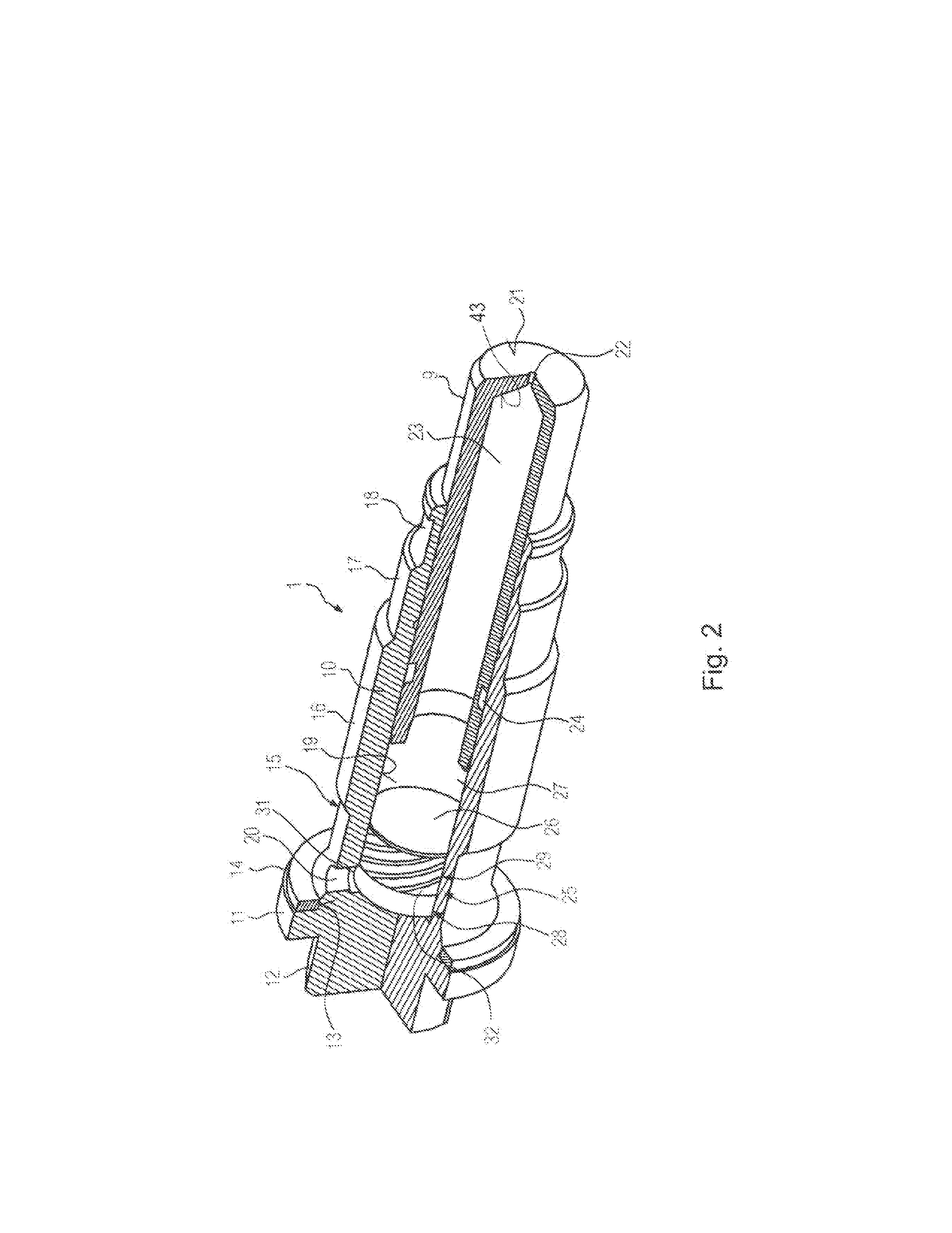
[0029]FIG. 2 a perspective cross-section view of the screw-in chain tensioner from FIG. 1, where the supply insert is not shown as a cross-section,

[0030]FIG. 3 the back end of the chain tensioner from FIG. 2 in a perspective cross-section diagram, where the supply insert is also shown as a corresponding cross-section,

[0031]FIG. 4 a perspective diagram of the supply insert from FIG. 2 seen from the front, showing the front face,

[0032]FIG. 5 the supply insert from FIG. 4 in a perspective diagram seen from the back,

[0033]FIG. 6 a perspective drawing of a tension spring for use in a screw-in chain tensioner per FIG. 2,

[0034]FIG. 7 a perspective drawing of a packing for use in a screw-in chain tensioner per FIG. 2,

[0035]FIG. 8 a diagram regarding the distribution of the drainage flow from the pressure reservoir as a function of various piston stroke frequencies for the first embodiment,

second embodiment

[0036]FIG. 9 a perspective cross-section view of the screw-in chain tensioner from FIG. 1, where the supply insert is not shown as a cross-section,

[0037]FIG. 10 the back end of the chain tensioner from FIG. 2 in a perspective cross-section diagram, where the supply insert is also shown as a corresponding cross-section,

[0038]FIG. 11 a perspective diagram of the supply insert from FIG. 9 seen from the front, showing the front face,

[0039]FIG. 12 the supply insert from FIG. 11 in a perspective diagram seen from the back,

[0040]FIG. 13 a diagram regarding the distribution of the drainage flow from the pressure reservoir as a function of various piston stroke frequencies for the second embodiment,

[0041]FIG. 14 a diagram showing the distribution of the inflow into the pressure reservoir as a function of various piston stroke frequencies for the second embodiment,

[0042]FIG. 15 a first embodiment of a tensioning device series in a perspective cross-section diagram, where the supply inserts ar...


PUM


Abstract

The damping device of the tensioning device has at least one damping channel that is open in both flow directions as a component of the fluid supply in such a way that during operation at least a portion of the supply stream is fed through the at least one damping channel into the pressure reservoir, and the damping device and the venting device are coupled with each other by fluid engineering means such that a drainage flow from the pressure reservoir occurs via the damping device and the venting device in combination, and the supply flow occurs predominantly independently of the venting device.

Description

CROSS-REFERENCE TO RELATED APPLICATION[0001]This application claims priority to foreign German patent application No. DE 10 2011 122 185.2, filed on Dec. 23, 2011, the disclosure of which is incorporated by reference in its entirety.FIELD OF THE INVENTION[0002]The present invention refers to a tensioning device for a flexible drive device, such as chains or belts, with a housing, a tensioning piston that slides inside the housing, a hydraulic fluid pressure reservoir configured between the housing and the tensioning piston, a fluid supply arranged in the housing to supply the pressure reservoir with hydraulic fluid, a damping device that damps the retracting motion of the tensioning piston, where said damping device has a physical fluid connection to the pressure reservoir, and a venting device that is arranged on the tensioning piston or between the tensioning piston and housing, where said venting device has a physical fluid connection to the pressure reservoir.BACKGROUND AND SUMM...

Claims


Application Information

Patent Timeline
Patent Type & Authority Applications(United States)
IPC IPC(8): F16H7/08
CPCF16H7/0836F16H7/0831F16H2007/0893F16H2007/0812F16H2007/0817F16H2007/0806
Inventor PERISSINOTTO, RENZOSCHELZIG, ULRICH
Owner IWIS MOTORSYSTEME GMBH & CO KG
Why Eureka
Try Eureka