Umbilical splint and method of use

a splint and splint technology, applied in the field of splints, can solve the problems of difficult to ensure sterility, difficult to keep marbles in place, and deformities of the umbilicus, and achieve the effects of reducing the formation and/or appearance of scars, reducing the formation of pressure, and reducing the formation of scars

a splint and splint technology, applied in the field of splints, can solve the problems of difficult to ensure sterility, difficult to keep marbles in place, and deformities of the umbilicus, and achieve the effects of reducing the formation and/or appearance of scars, reducing the formation of pressure, and reducing the formation of scars

US20130178873A1Inactive Publication Date: 2013-07-11VEKIOS ROULA +1

Image

  • Umbilical splint and method of use
  • Umbilical splint and method of use
  • Umbilical splint and method of use

Examples


Embodiment Construction

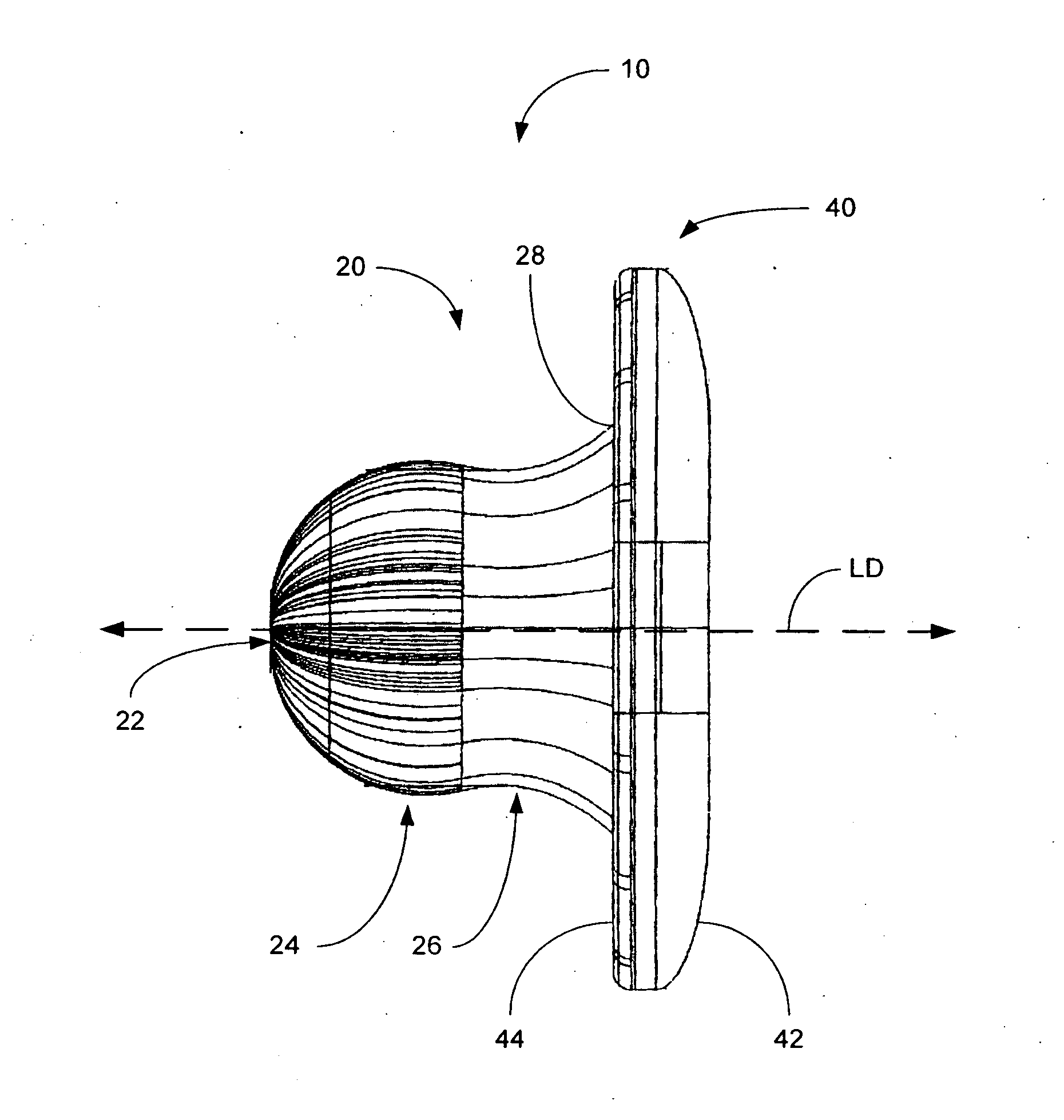
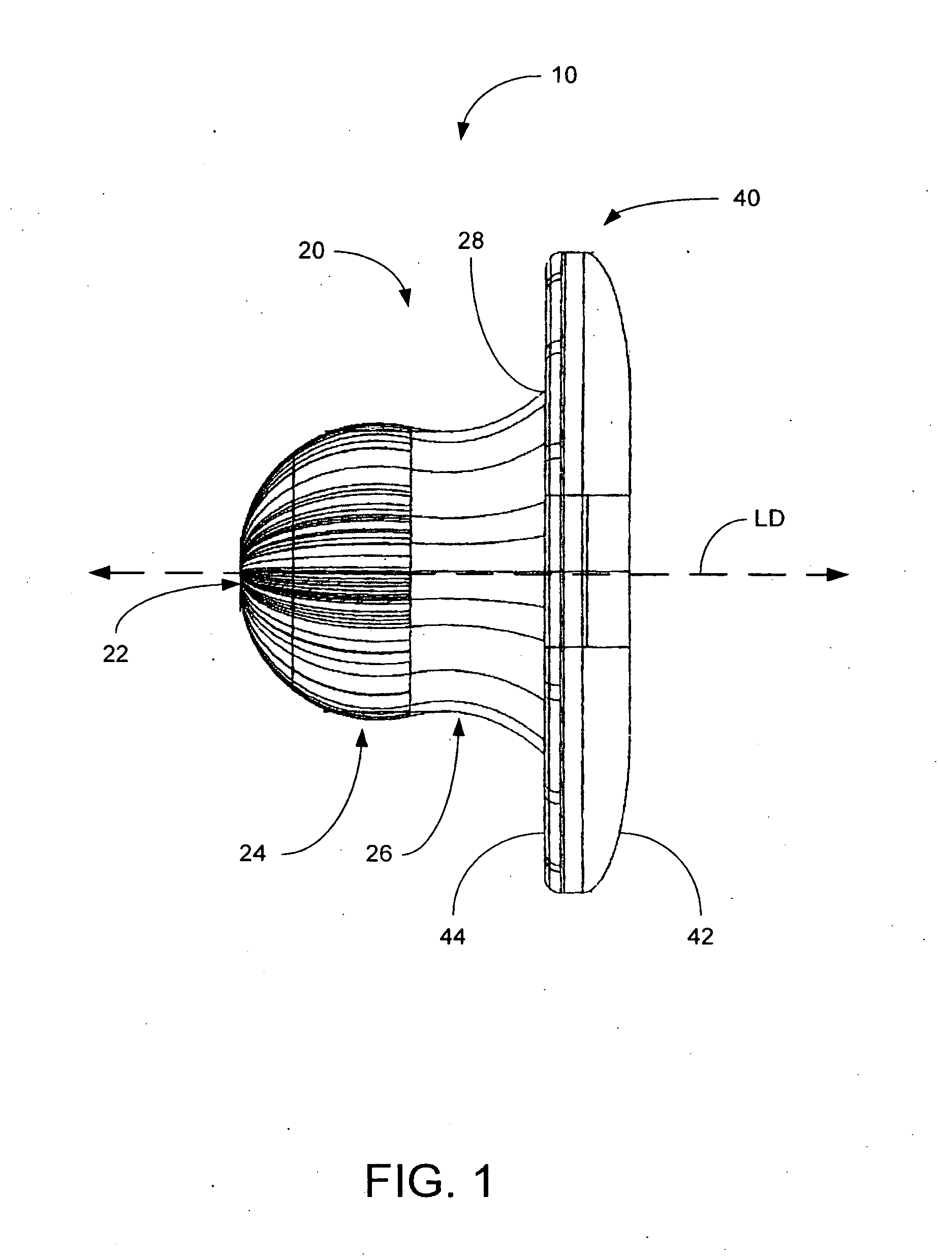
[0041]Referring now to FIG. 1, an umbilical splint 10 is shown in accordance with an embodiment of the present invention. The umbilical splint 10 is configured with an insertion portion 20 terminating at an insertion end 22 and an external flange 40.

[0042]The insertion portion 20 extends in a longitudinal direction LD, shown in dashed lines, for insertion into an umbilicus. The insertion portion 20 includes an insertion end 22, a bulbous section 24 and a retaining section 26. The bulbous section 24 is disposed between the insertion end 22 and the retaining section 26.

[0043]The umbilical splint 10 may also include an external flange 40. The external flange 40 is configured with an external surface 42 and an underside surface 44. The underside surface 44 of the external flange 40 faces the insertion end 22 of the insertion portion 20. The insertion portion 20 and the external flange 40 may be joined at an intersection 28.

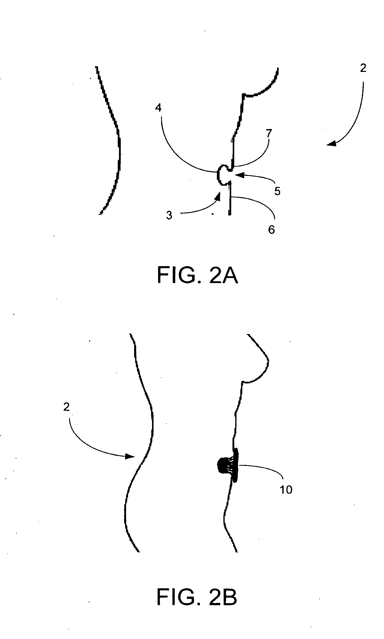
[0044]As seen in FIG. 2A, a patient 2 has an umbilicus 3 (i.e. a...


PUM


Abstract

A use of an umbilical splint for shaping an umbilicus after an abdominal operation is described. The umbilical splint may comprise an insertion portion extending in a longitudinal direction and terminating at an insertion end for insertion into the umbilicus. Furthermore, the insertion portion may comprise a bulbous section near the insertion end. The bulbous section may be operable to apply pressure to a tissue of the umbilicus after the abdominal operation. The insertion portion may have different cross-sectional shapes including circular and oval. Finally, the insertion portion may be configured to engage the umbilicus such that the umbilical splint is retained within the umbilicus.

Description

FIELD OF THE INVENTION[0001]This invention relates to an umbilical splint, and more particularly towards an umbilical splint for post-operative care and methods of use.BACKGROUND OF THE INVENTION[0002]During certain types of abdominal surgery, incisions are made in the umbilicus or the surrounding umbilical (belly button) region. Examples of such procedures include abdominoplasty (i.e. tummy tuck), panniculectomy, Transverse Rectus Abdominis Myocutaneous (TRAM) flap procedures, endoscopic surgeries, and the like. Circumferential umbilical incisions can lead to contracture and closure of the umbilicus or umbilical opening due to the physiological forces of scar contracture. This can lead to deformities of the umbilicus, as well as infections.[0003]Deformity of the umbilicus can also occur after pregnancy, especially if a caesarean section is required, and after weight loss.[0004]Current products used to counteract the forces of scar contracture following umbilical or other abdominal ...

Claims


Application Information

Patent Timeline
11 Jul 2013
Publication
US20130178873A1
IPC
A61B17/08
CPC
A61B17/08; A61B2017/00637; A61B17/0057; A61F5/30; A61B2017/00654; A61B2017/00659; A61B2017/00893
Inventors
VEKIOS, ROULA; MEATHREL, KIMBERLEY