Silo combustion chamber for a gas turbine

a combustion chamber and gas turbine technology, which is applied in the combustion chamber, continuous combustion chamber, combustion process, etc., can solve the problems of increasing the investment cost of a plant, increasing the complexity of the system, and many existing thermal power plants with gas turbines cannot be readily retrofitted with a steam circuit, etc., to achieve the effect of improving the efficiency of the combustion chamber, and reducing the cost of gas turbines

Inactive Publication Date: 2017-05-11
SIEMENS AG
View PDF6 Cites 1 Cited by
  • Summary
  • Abstract
  • Description
  • Claims
  • Application Information

AI Technical Summary

Benefits of technology

[0025]In this context, the or each connecting stub advantageously has at least one expansion compensator. An expansion compensator makes it possible to equalize thermal stresses at a connecting stub, which can arise as a consequence of the different temperatures of the working gas inside the connecting stub and the working gas in the cavity flowing around the outside of the connecting stub. The pre-compressed working gas in the cavity can be at a temperature of 350° C.-400° C., while the heat exchanger heats the working gas to up to 550° C.
[0026]In this context, it is of additional advantage if the flame tube base has a multiplicity of bores. Bores of this type allow pre-compressed working gas to flow, as a consequence of the pressure difference and in small quantities, from the cavity into the combustion chamber, where it contributes to cooling the material of the flame tube base. This reduces the temperature for which materials used for the flame tube base need to be designed.
[0027]The inner wall advantageously has a multiplicity of bores. This reduces the temperature for which materials used for the inner wall need to be designed.
[0028]Expediently, the flame tube is essentially cylindrical. This is to be understood as a right cylinder whose base is axisymmetric or has high-order rotational symmetry. Such a shape permits particularly simple construction with a relatively advantageous pressure distribution both in the cavity and in the combustion space.
[0029]In this context, the arrangement of the or each burner in the flame tube base is in particular rotationally symmetric, which has a positive effect on the pressure distribution in the combustion space and promotes an even mass flow in each burner. This is advantageous for the expansion of the working gas which is mixed with fuel and burned, and thus contributes to an advantageous degree of efficiency.
[0030]In a further advantageous embodiment of the invention, the outer wall comprises a hood that is flanged onto the outer wall and extends over the region above the flame tube base. In particular, such a hood makes it possible to route a fuel line to a burner and connecting stubs from the annular chamber to a burner, or connecting parts from the annular chamber to the plenum chamber, and to provide other openings for the projecting portion of the or each burner. These measures simplify, in particular, the retrofitting of an existing gas turbine for use with a heat exchanger.

Problems solved by technology

However, this improvement in efficiency implies an increase in the system complexity, since it is now necessary to connect the entire steam circuit to the gas turbine and to coordinate it with the latter in terms of control, all of which increases the investment costs for a plant.
In addition, many existing thermal power plants with gas turbines cannot readily be retrofitted with a steam circuit due to the dimensions of the components of the latter.
In this context, one unsolved problem arises from the technical implementation of the integration in particular of an existing gas turbine system into a recuperator process, wherein the recirculation of the working gas from the heat exchanger is of particular significance here.

Method used


Image

  • Silo combustion chamber for a gas turbine
  • Silo combustion chamber for a gas turbine
  • Silo combustion chamber for a gas turbine

Examples


Embodiment Construction

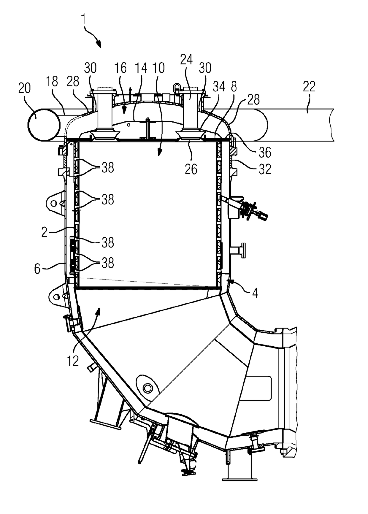
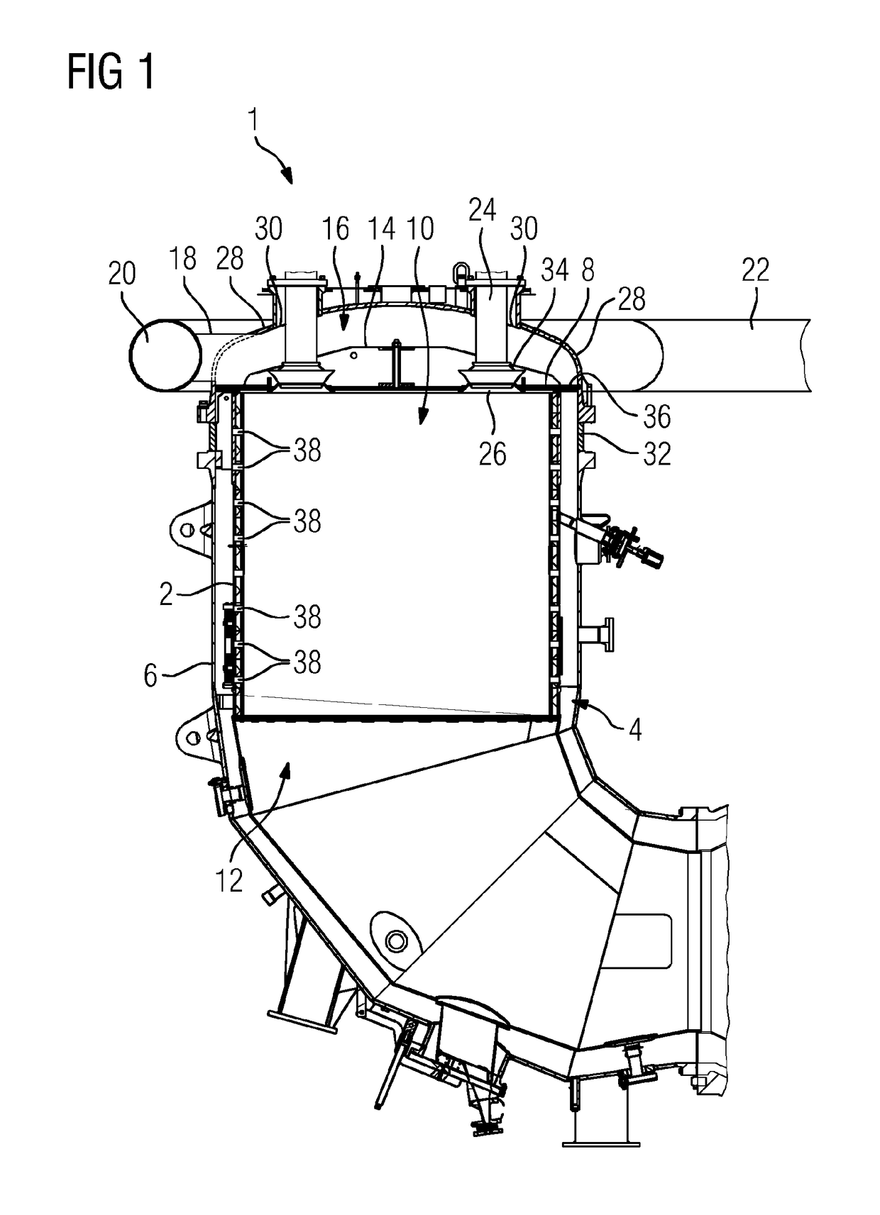
[0039]FIG. 1 shows, in a cross-sectional representation, a silo combustion chamber 1 for a gas turbine which is not shown in greater detail. The silo combustion chamber 1 comprises an inner wall 2 which is surrounded by an outer wall 6, forming a cavity 4. The inner wall 2, with the adjoining flame tube base 8, bounds the essentially cylindrical combustion space 10 of the flame tube 12. On that side of the flame tube base 8 which is oriented away from the combustion space 10 and is reinforced there by a supporting structure 14, there is arranged a plenum chamber 16 that is connected, via connecting parts 18, to an annular chamber 20 that surrounds the silo combustion chamber 1 outside the outer wall 6. An inflow line 22 leads from a recuperator (not shown in the drawing) to the annular chamber 20. The burners 24 open, from the plenum chamber 16, via openings 26 into the combustion chamber 10.

[0040]The plenum chamber 16 is bounded, above the burner 24, by a flanged-on hood 28 in whic...


PUM


Abstract

A silo combustion chamber for a gas turbine having a flame tube having an inner wall and flame tube base delimiting a combustion chamber; an outer wall surrounding the inner wall, forming a cavity; an annular chamber at least partly surrounding the outer wall and a number of supply lines fluidically coupled to the hot side of a heat exchanger during operation of the turbine; a number of burners, each of which opens into the combustion chamber on the outlet side through an opening in the flame tube base. The oxygen supply is fluidically connected to the annular chamber. A collecting chamber is arranged over the flame tube base. The annular chamber is connected to the collecting chamber via each connecting piece, each burner is fluidically connected to the collecting chamber to supply oxygen. The cavity between the inner and outer wall is locally fluidically separated from the collecting chamber.

Description

CROSS REFERENCE TO RELATED APPLICATIONS[0001]This application is the U.S. National Stage of International Application No. PCT / EP2015 / 055799 filed Mar. 19, 2015, and claims the benefit thereof. The International Application claims the benefit of European Application No. EP14162721 filed Mar 31, 2014. All of the applications are incorporated by reference herein in their entirety.FIELD OF INVENTION[0002]The invention relates to a silo combustion chamber for a gas turbine, comprising a flame tube formed by an inner wall and a flame tube base and bounding a combustion space, an outer wall that surrounds the inner wall, forming a cavity, and a number of burners which each open, on the outlet side, into the combustion space via an opening in the flame tube base.BACKGROUND OF INVENTION[0003]In a gas turbine, the combustion heat of a fuel is converted into mechanical work. The thermodynamic cycle that describes this conversion corresponds approximately to the Joule cycle.[0004]In that contex...

Claims


Application Information

Patent Timeline
Patent Type & Authority Applications(United States)
IPC IPC(8): F23R3/04F23R3/42
CPCF23R3/045F23R2900/03342F23R3/42F23R2900/00001F02C7/10F23R3/002
Inventor WILKE, MARTIN
Owner SIEMENS AG
Why Eureka
Try Eureka