

A control method for interlaced phase shifting of a photovoltaic inverter and a photovoltaic inverter
A photovoltaic inverter, interleaved phase-shifting technology, applied in photovoltaic power generation, output power conversion devices, AC power input conversion to DC power output, etc., can solve the impact of system stability and rapidity, and increase system timer resources , system resource constraints and other issues, to achieve high reliability, increase power density, and prolong life
- Summary
- Abstract
- Description
- Claims
- Application Information
AI Technical Summary
Problems solved by technology
Method used
Image

Examples
Embodiment
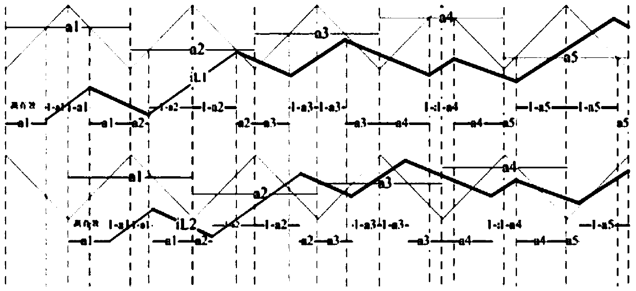
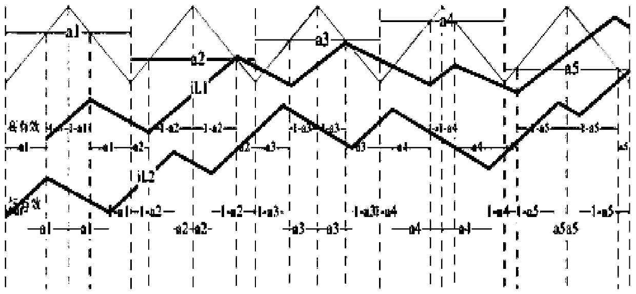
[0040] The basic idea of the technical solution of the present invention (take 2 channels as an example):
[0041] The two channels use the same timer, set the high and low active levels in the program to be different, and modify the system action time to be within (the conduction time is 2*(1-a(N))*Ts, of which 1-a(N ) is the conduction duty cycle, Ts is the switching period). In the increasing and decreasing counting mode, the inverter does not consider the conduction loss, turn-off loss, diode and open tube voltage drop, etc. According to the high level effective analysis:
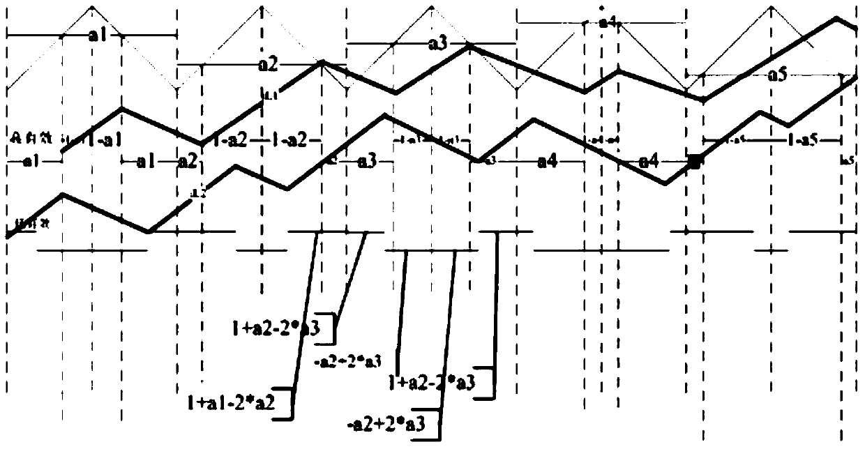
[0042] In an up-down counting process, the on-time is 2*(1-a(N))*Ts, and the off-time is 2*a(N)*Ts (on the contrary, according to the low-level effective analysis, in an actual increment In the process of counting down, the on-time is 2*(1-a(N))*Ts, and the off-time is 2*a(N)*Ts, the action time of both is the same in the process).
[0043] According to the different ways of sending waves, assume t...
PUM
 Abstract
Description
Claims
Application Information