Control apparatus for vehicle automatic transmission

a technology of automatic transmission and control apparatus, which is applied in the direction of mechanical control devices, fluid couplings, instruments, etc., can solve the problems of inability to ensure good drivability, inability to perform downshift and shift hold, and inability to implement downshift and subsequent shift hold at timing

Active Publication Date: 2013-07-11
HONDA MOTOR CO LTD
View PDF3 Cites 17 Cited by
  • Summary
  • Abstract
  • Description
  • Claims
  • Application Information

AI Technical Summary

Benefits of technology

[0024]In accordance with the control apparatus for a vehicle automatic transmission according to the present invention, the running on the meandering road (winding road), for which the downshift and the shift hold after the downshift concerned should be implemented, is appropriately sensed, whereby the downshift and the shift hold can be implemented at more appropriate timing.

Problems solved by technology

However, if the downshift on the places other than the downhill road is implemented only at the time of the sudden deceleration of the vehicle as described above, then it is apprehended that, at timing when the downshift and a shift hold after the downshift should be originally performed in such an event where the vehicle runs on a continuously meandering road (winding road), appropriate downshift and shift hold may not be performed, and good drivability may not be able to be ensured.
Moreover, if the determination of the downshift and the subsequent shift hold is made based on a variation of the opening degree of the accelerator pedal, then it is apprehended that, in a drive of a driver whose operation of the accelerator pedal is violent (rough), the downshift and the shift hold may be implemented at timing when the downshift and the shift hold are unnecessary.
Moreover, in a drive of a driver highly skilled in driving, whose operation of the accelerator pedal is gentle, it is apprehended that the downshift and the subsequent shift hold may not be implemented at timing when the downshift and the shift hold are originally necessary.
That is to say, there is a disadvantage that the timing of the downshift and the shift hold is undesirably decided only by an operation manner of the driver irrespective of a running environment such as type of a road surface on which the vehicle runs.
Meanwhile, if the downshift is implemented early in the normal running mode, then an increase of the number of engine revolutions is brought about, and it is apprehended that the increase concerned may result in feeling of wrongness about drivability, such as worsening of vibrations / noise of the vehicle, and an increase of the engine brake.

Method used


Image

  • Control apparatus for vehicle automatic transmission
  • Control apparatus for vehicle automatic transmission
  • Control apparatus for vehicle automatic transmission

Examples


first embodiment

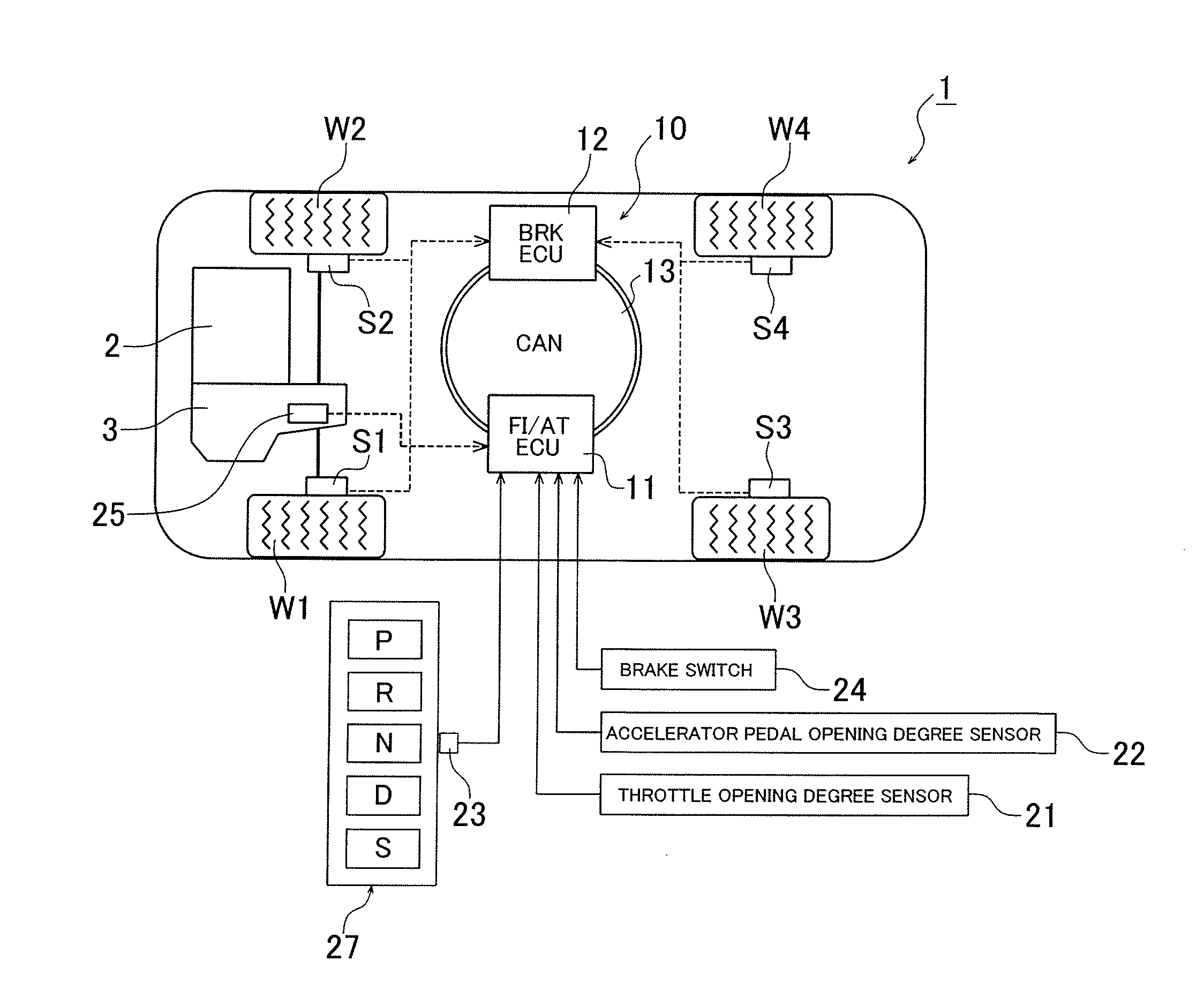
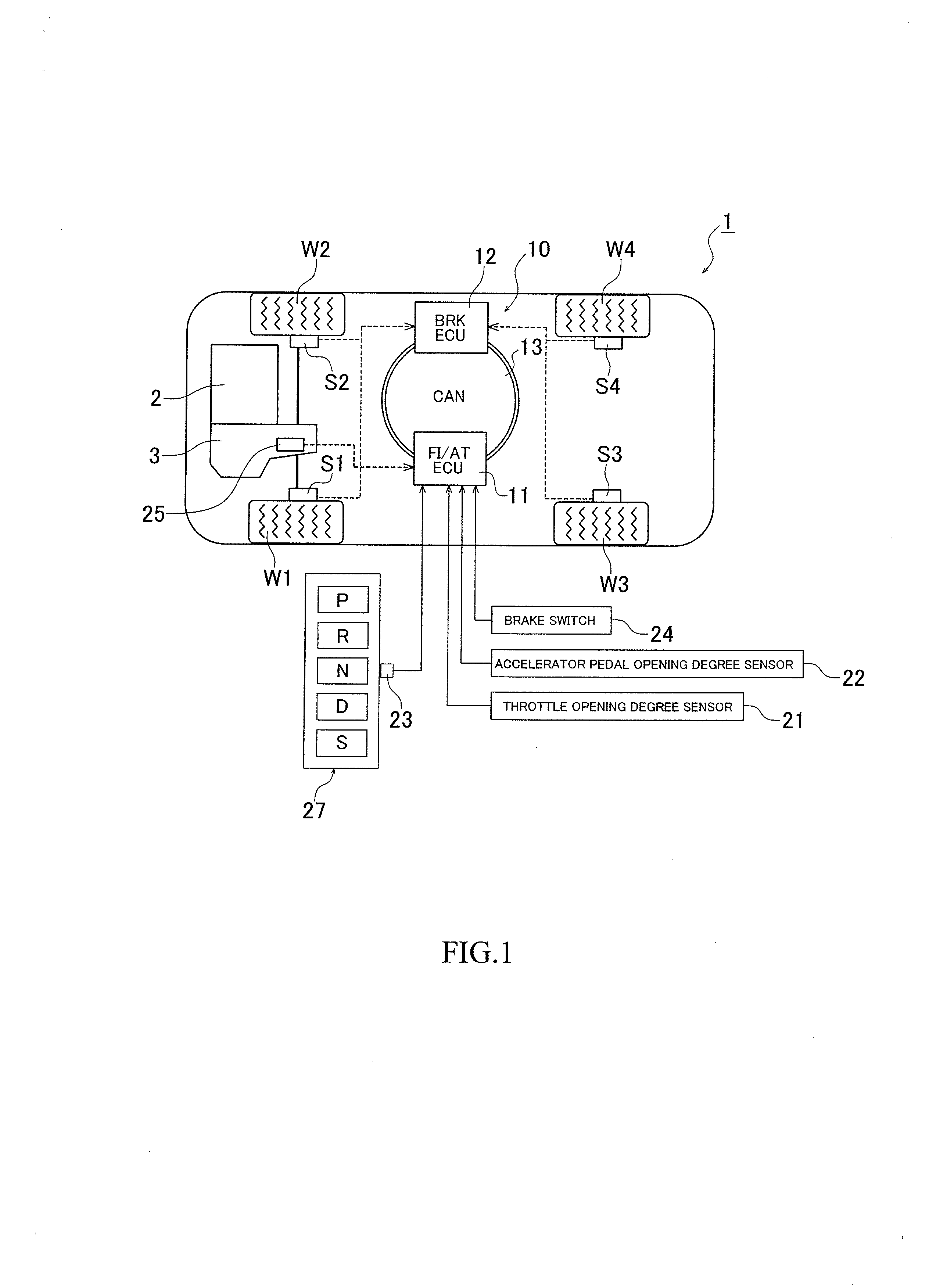
[0041]FIG. 1 is a view showing a schematic configuration of a vehicle including a control apparatus for a vehicle automatic transmission according to an embodiment of the present invention. A vehicle 1 shown in FIG. 1 includes: an engine 2; and an automatic transmission 3 having a multi-speed transmission gear mechanism, and an output of the engine 2 is transmitted through the automatic transmission 3 to driving wheels (front wheels) W1 and W2. Moreover, the vehicle 1 includes a control unit (ECU) 10 using a microcomputer for performing drive control for the vehicle 1. The control unit 10 includes: an FI / AT ECU 11 for performing control for the engine 2 and the automatic transmission 3; and a brake ECU (or VSA ECU) 12 for performing behavior control for the vehicle, which includes control for a brake. Then, these FI / AT ECU 11 and brake ECU 12 are connected to each other through a CAN (controller area network) 13.

[0042]To the control unit 10, there are inputted signals coming from a ...

second embodiment

[0061]Next, a description is made of a second embodiment of the present invention. Note that, in the description of the second embodiment and the drawings corresponding thereto, the same reference numerals are assigned to the same or equivalent constituent portions as or to those of the first embodiment, and a detailed description of the portions concerned is omitted below. Moreover, matters other than matters to be described below are the same as those of the first embodiment. This point also applies to other embodiments in a similar way.

[0062]FIG. 8 is a conceptual view showing a calculation procedure of the sport running estimated value LEVELSP in the second embodiment. In the first embodiment, the sport running estimated value LEVELSP is calculated based on the average value |ΔTH|AVE of the accelerator pedal opening degree changes and on the average value |ΔV|AVE of the changes of the vehicle speed V, and meanwhile, in this embodiment, as shown in FIG. 8, the sport running estim...


PUM


Abstract

A sport running estimated value LEVELSP obtained by searching a value on a map prepared in advance based on an average values AGYAVE of lateral accelerations GY of a vehicle and on average values of vehicle speed changes is calculated, and a vehicle speed on a shift map is searched based on the sport running estimated value LEVELSP and an estimated value DA of a vehicle gradient, whereby a downshift vehicle speed VA at which a downshift is implemented is calculated. Then, the downshift is implemented in a case where actuation of a brake is detected, deceleration of the vehicle is a predetermined value or more, and a current vehicle speed is a downshift vehicle speed VA or more. In such a way, running on a meandering road, for which the downshift and a subsequent shift hold should be implemented, is sensed appropriately.

Description

REFERENCE TO RELATED APPLICATIONS[0001]This disclosure relates to a theme included in Japanese Patent Application No. 2012-002626 filed on Jan. 10, 2012, and a whole of a disclosure thereof is explicitly incorporated by reference in this application.BACKGROUND OF THE INVENTION[0002]1. Technical Field of the Invention[0003]The present invention relates to a control apparatus for a vehicle automatic transmission, and particularly, relates to a control apparatus for a vehicle automatic transmission, which performs an automatic downshift for speed gears according to needs at the time of implementing a manual shift mode of performing a shift operation instructed by a manual operation of a driver.[0004]2. Description of the Related Art[0005]As a control apparatus for a vehicle automatic transmission, an apparatus is general, which prepares in advance plural type of shift maps for obtaining shift characteristics, obtains a value indicating a running resistance through acceleration, determi...

Claims


Application Information

Patent Timeline
Patent Type & Authority Applications(United States)
IPC IPC(8): B60W10/11
CPCB60W10/11F16H61/0213F16H59/0204F16H59/54F16H61/21Y10T477/634Y10T477/6347Y10T74/20085Y10T74/19251Y10T477/60Y10T477/63378Y10T477/6242
Inventor ISHIKAWA, YUTAKASAITO, HIROSHIGOKAN, YASUHIRO
Owner HONDA MOTOR CO LTD
Why Eureka
Try Eureka