Pivot bearing with turned damper clamping
- Summary
- Abstract
- Description
- Claims
- Application Information
AI Technical Summary
Benefits of technology
Problems solved by technology
Method used
Image
Examples
Embodiment Construction
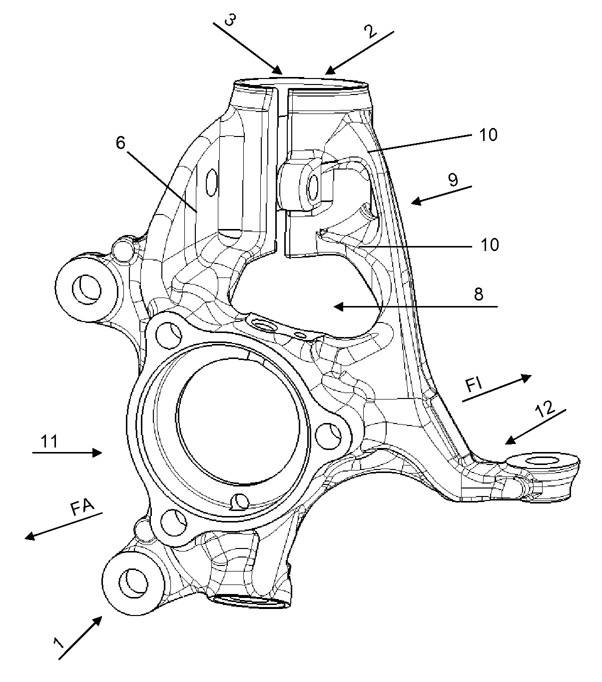
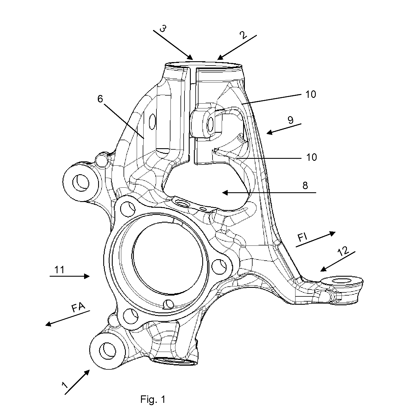
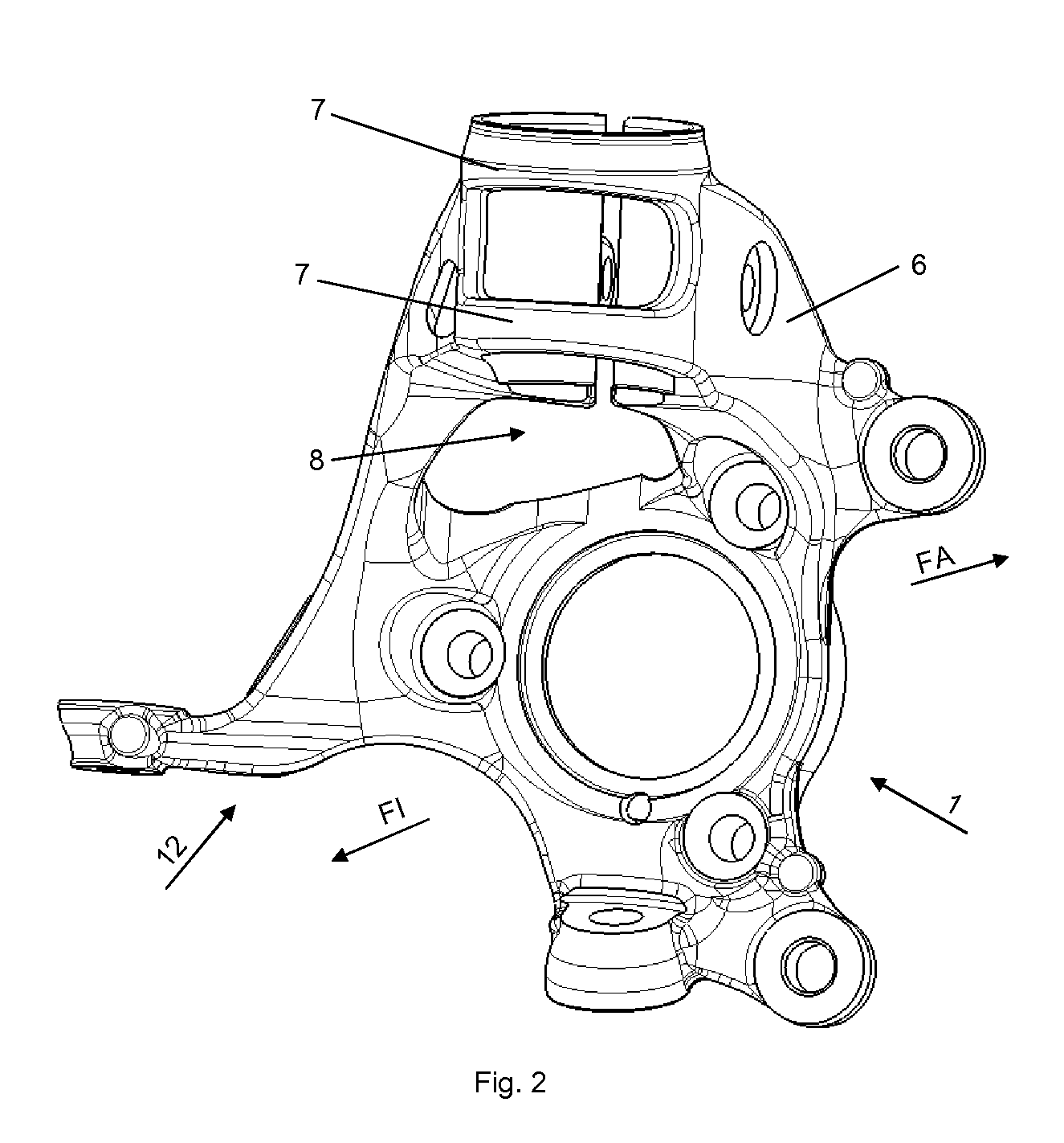
[0019]FIG. 1 shows a pivot bearing 1 according to the invention. The wheel bearing receiver 11 serves for installation of a wheel bearing (not shown). The arrow directions FA and FI shown in the drawings point respectively towards the vehicle outside FA and the vehicle inside FI when the pivot bearing 1 is in fitted state. The spring strut receiver 2 arranged on the pivot bearing 1 serves for fixing of the spring strut or shock absorber (not shown). The damper clamping 3 on the pivot bearing 1 according to the invention is arranged on the spring strut receiver 2 in the direction of the vehicle outside FA. In conventional pivot bearings, the clamping usually takes place on the vehicle inside of the pivot bearing. In order to make the pivot bearing 1 as light as possible, all unnecessary material has been omitted and existing structures are utilised repeatedly in their function. Thus the carrier rib 6 also serves as a support surface 14 for the clamping element 13. Firstly this avoids...
PUM
| Property | Measurement | Unit |
|---|---|---|
| Diameter | aaaaa | aaaaa |
| Ductility | aaaaa | aaaaa |
Abstract
Description
Claims
Application Information
 - R&D
- Intellectual Property
- Life Sciences
- Materials
- Tech Scout
- Unparalleled Data Quality
- Higher Quality Content
- 60% Fewer Hallucinations
Browse by: Latest US Patents, China's latest patents, Technical Efficacy Thesaurus, Application Domain, Technology Topic, Popular Technical Reports.
© 2025 PatSnap. All rights reserved.Legal|Privacy policy|Modern Slavery Act Transparency Statement|Sitemap|About US| Contact US: help@patsnap.com


