Auxiliary frame for improving conventional frame and method for working the same

a technology of auxiliary frame and conventional frame, which is applied in the direction of girders, joists, transoms, etc., can solve the problems of wasting time, labor and material, and causing many inconveniences

Inactive Publication Date: 2002-02-05
LIN CHUN CHEN
View PDF13 Cites 37 Cited by
  • Summary
  • Abstract
  • Description
  • Claims
  • Application Information

AI Technical Summary

Problems solved by technology

For a conventional frame made of wood, all wall material and floor material must be discarded after it has rotted, thereby wasting much time, labor, and material.
Also, the working environment will be very dirty and result in much inconvenience.

Method used


Image

  • Auxiliary frame for improving conventional frame and method for working the same
  • Auxiliary frame for improving conventional frame and method for working the same
  • Auxiliary frame for improving conventional frame and method for working the same

Examples


Embodiment Construction

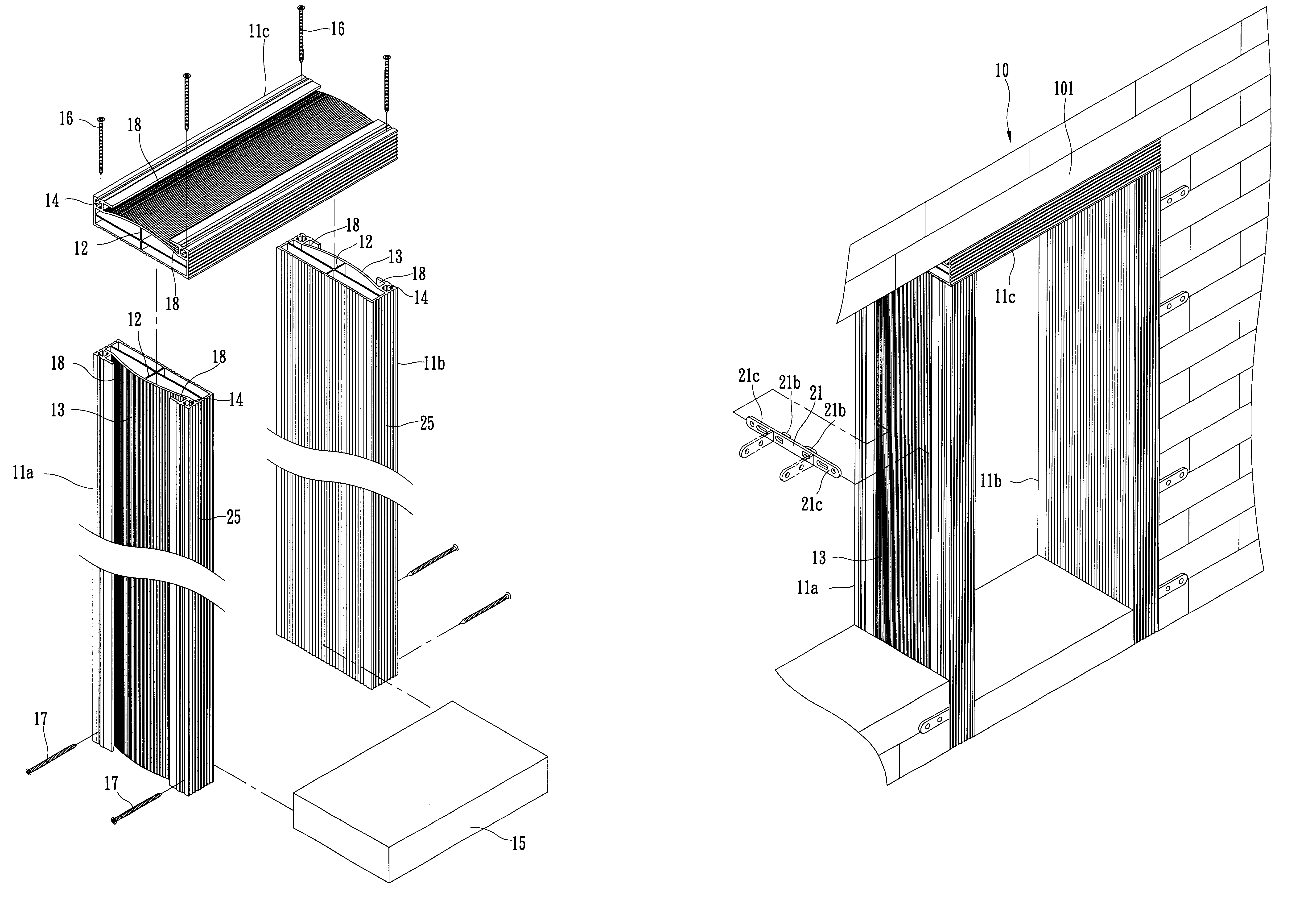
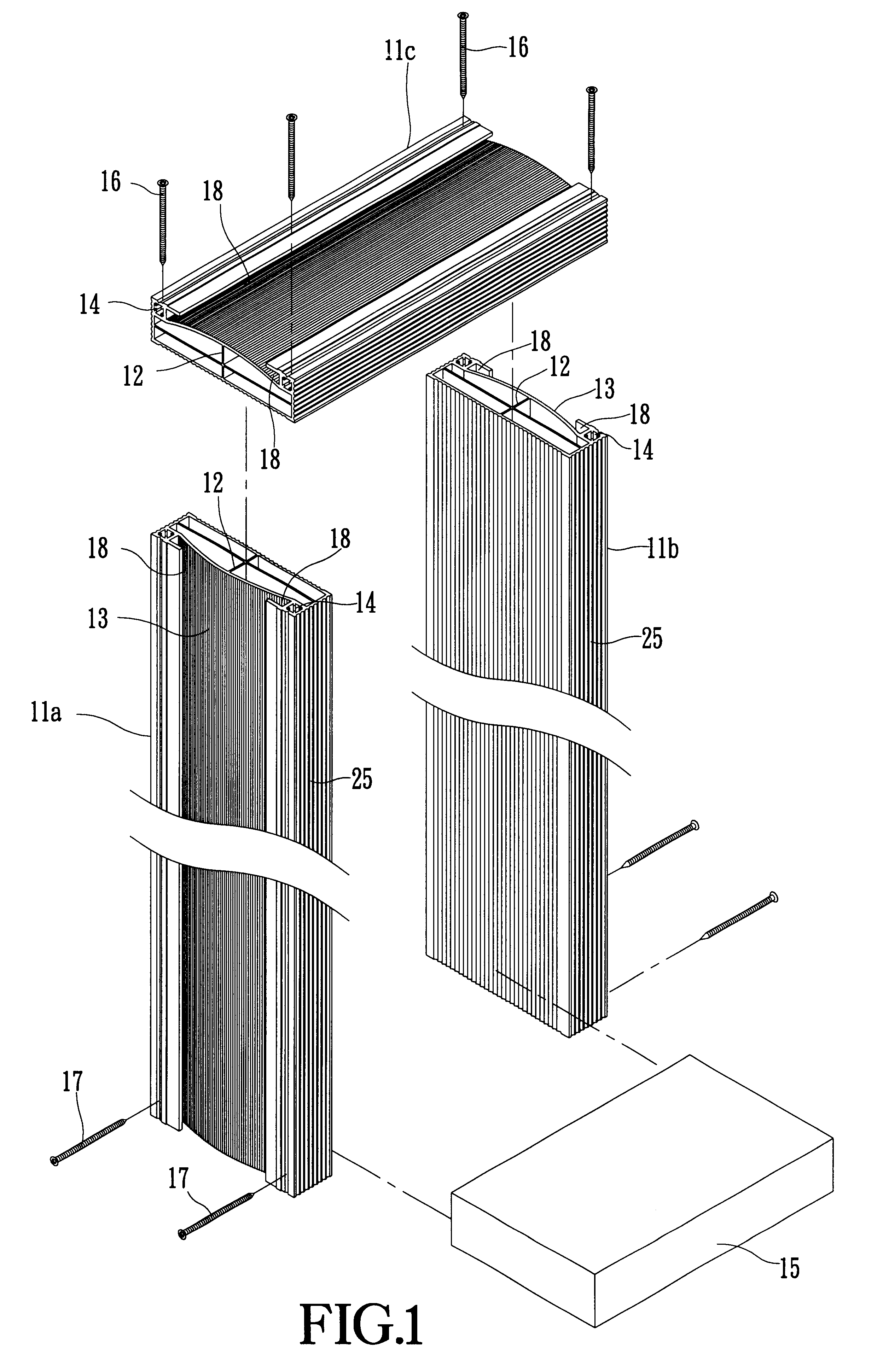
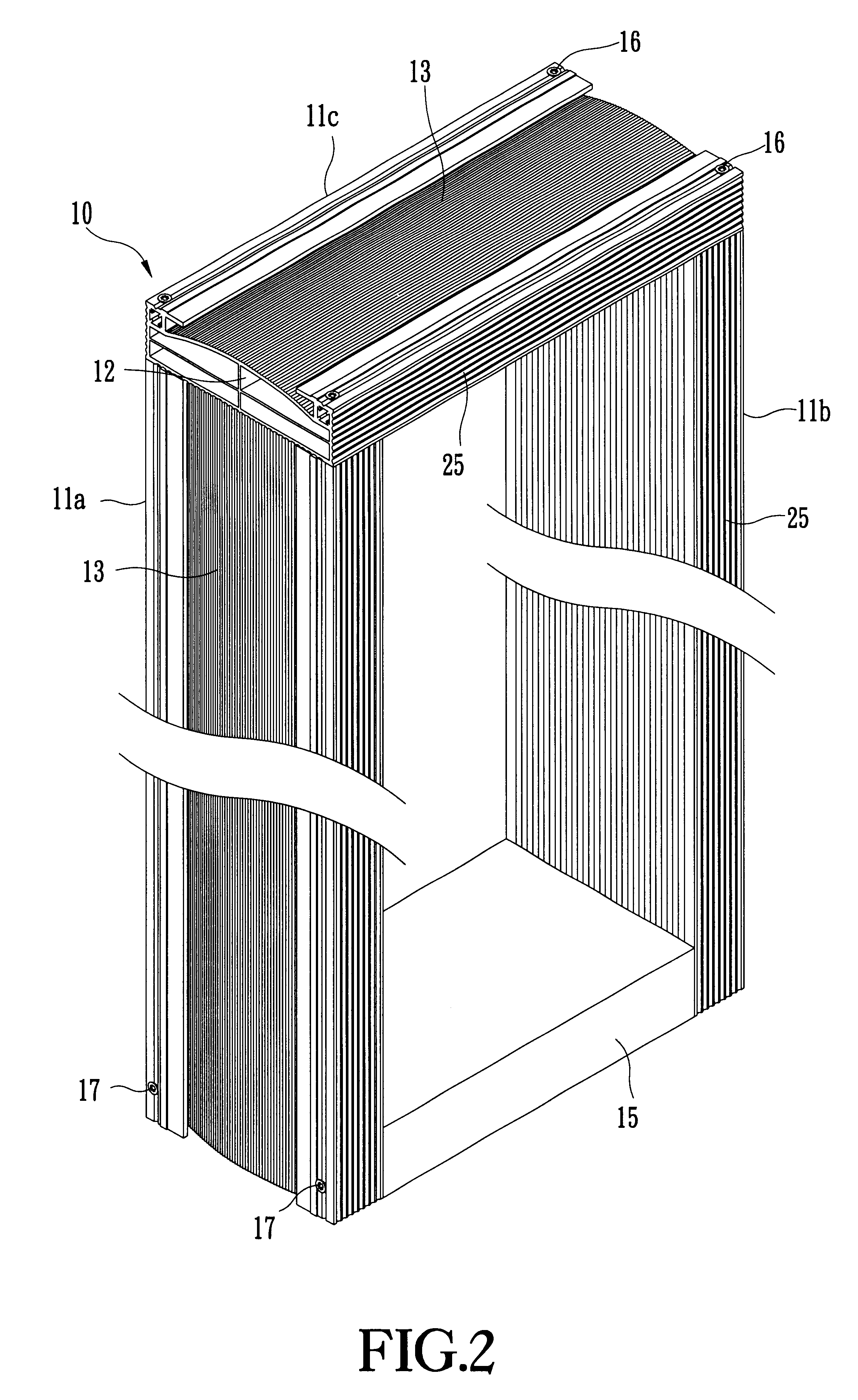
As shown in FIGS. 1 and 2, the present invention provides an auxiliary frame for improving a conventional frame. The proposed auxiliary frame 10 comprises three frame bars 11a, 11b, and 11c. The three frame bars 11a, 11b, and 11c are made of plastic or metallic material, each being of a predetermined length. Each of the three frame bars 11a, 11b, and 11c has a hollow inside and has a crossed reinforcing rib 12 installed therein (Please also refer to FIG. 12). One side of each of the three frame bars 11a, 11b, and 11c forms an embowed reinforcing girder 13 to achieve better reinforcing effect. A through hole 14 and a snap groove 18 are disposed at each side of the reinforcing girder 13. The two frame bars 11a and 11b are disposed at opposite sides, while the frame bar 11c is disposed at the top end of the two frame bars 11a and 11b, thereby forming the reversely U-shaped auxiliary frame 10. A fixing element 15 is installed between the bottom end of the two frame bars 11a and 11b. The...


PUM


Abstract

The auxiliary frame has a plurality of frame bars made of plastic or metallic material. Each of the frame bars has a hollow inside and has a crossed reinforcing rib installed therein. One side of each of the frame bars forms an embowed reinforcing girder to achieve better reinforcing effect. A through hole and a snap groove are disposed at each side of the reinforcing girder. Two of the frame bars are disposed at opposite sides, while another frame bar is disposed at the top ends of the two frame bars. A fixing element is installed between the bottom ends of the two frame bars at two sides. The two ends of the frame bar at top end are screwed with the two frame bars via a plurality of screws vertically penetrating the through holes at the top ends of the two frame bars. The bottom ends of the two frame bars are screwed with the two ends of the fixing element via a plurality of screws vertically penetrating the through holes at the bottom ends of the two frame bars.

Description

The present invention relates to an auxiliary frame for improving a conventional frame and a method for working the same and, more particularly, to an auxiliary frame and a method for working the same, which has good moisture-proof and waterproof effects, and can be maintained more conveniently.Conventional frames such as doorframes are generally made of wood having inferior strength and bad moisture-proof and waterproof effects so that they can easily rot, resulting in much limited usage. Moreover, doorframes made of wood consume much natural wood material. Their fireproof effect is bad. Additionally, after doorframes made of wood has rotted, all wall material and floor material must be discarded, thereby wasting much time, labor, and material. Also, the working environment will be very dirty and result in much inconvenience.SUMMARY AND OBJECTS OF THE PRESENT INVENTIONThe primary object of the present invention is to provide an auxiliary frame for improving a conventional frame, wh...

Claims


Application Information

Patent Timeline
Patent Type & Authority Patents(United States)
IPC IPC(8): E04C3/02E06B1/00E04C3/38E06B1/02
CPCE04B1/7046E04C3/02E06B1/02E04C3/38E04C2003/023
Inventor LIN, CHUN-CHEN
Owner LIN CHUN CHEN
Why Eureka
Try Eureka