
High Torque Low Inductance Rotary Actuator

Active Publication Date: 2013-07-18
BENNER JR WILLIAM R
View PDF9 Cites 14 Cited by
  • Summary
  • Abstract
  • Description
  • Claims
  • Application Information

AI Technical Summary

Benefits of technology

The present invention relates to an electromechanical rotary actuator that can generate bidirectional torque for controlled rotation. The actuator includes a stator and a rotor, with one or more slots for placing coils and a rotor position restoring means to overcome cogging. The restoring means may include a magnet or a contoured cavity. The actuator has a non-uniform separation between the magnet and the teeth, which results in a spring-like return-to-center action of the rotor. The actuator also includes one or more slots for placing coils and may have a limited rotation.

Problems solved by technology

The non-uniform separation results in a greater separation proximate a central portion of the teeth contoured ends than the separation proximate the distal ends thereof.
The non-uniform separation provides a restoration torque resulting in a spring-like return-to-center action of the rotor.

Method used


Image

  • High Torque Low Inductance Rotary Actuator
  • High Torque Low Inductance Rotary Actuator
  • High Torque Low Inductance Rotary Actuator

Examples


Embodiment Construction

[0076]The present invention will now be described more fully hereinafter with reference to the accompanying drawings, in which preferred embodiments of the invention are shown. This invention may, however, be embodied in many different forms and should not be construed as limited to the embodiments set forth herein. Rather, these embodiments are provided so that this disclosure will be thorough and complete, and will fully convey the scope of the invention to those skilled in the art.

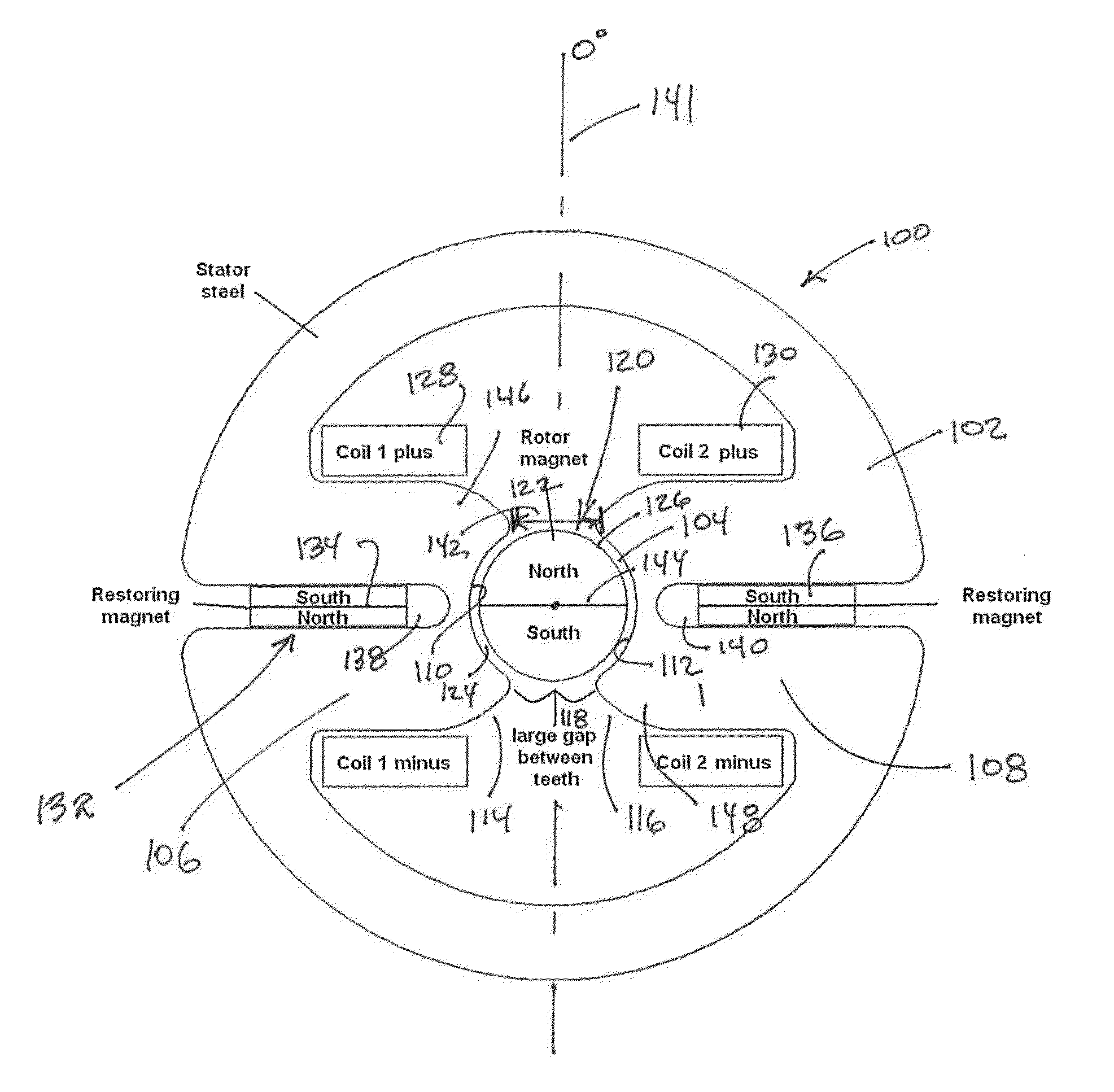
[0077]Referring initially to FIG. 9, one embodiment of the present invention is herein described as an electromechanical, limited rotation, rotary actuator 100. The actuator, herein described by way of example, comprises a stator 102 having an aperture 104 extending axially therein and at least two teeth 106, 108 having contoured ends 110, 112 forming at least a portion of the aperture. Distal ends 114, 116 of the teeth 106, 108 are in a spaced relationship and form a gap 118 therebetween. A rotor 120, ...


PUM


Abstract

An electromechanical rotary actuator includes a rotor and a stator having one or more slots into which one or more coils are placed. The stator includes a rotor position restoring means which overcomes cogging outside a desired rotation range. The rotor position restoration means may include one or more restoring magnets or optionally include a contoured cavity within the stator proximate the rotor. One stator includes teeth having contoured ends forming a portion of the aperture within which the rotor operates. Distal ends of the teeth form a relatively large gap compared to typical actuators, wherein the gap is sized to the rotor magnet. An actuator desirably having a high torque constant, low coil resistance and a low coil inductance is provided.

Description

CROSS REFERENCE TO RELATED APPLICATION[0001]This application claims priority to Application Serial No. 61 / 585,721, having filing date of Jan. 12, 2012 for High Torque Low Inductance Rotary Actuator Device and Associated Method, and is a continuation-in-part of application Ser. No. 13 / 446,437, having a filing date of Apr. 13, 2012 for Electromechanical Device and Assembly Method, which itself claims benefit of Application Ser. No. 61 / 539,172, having a filing date of Sep. 26, 2011, the disclosures of which are incorporated herein by reference, and commonly owned.FIELD OF THE INVENTION[0002]The present invention generally relates to limited angle electromechanical rotary actuators and in particular to actuators used in the field of optical scanning.BACKGROUND OF THE INVENTION[0003]Electromechanical rotary actuators have been in existence for decades. They are used in a variety of industrial and consumer applications, but they are particularly useful in the field of optical scanning, wh...

Claims


Application Information

Patent Timeline
IPC IPC(8): H02K1/17
CPCH02K33/16H02K1/148H02K1/146H02K1/17H02K21/046H02K2201/03
Inventor BENNER, JR., WILLIAM R.
Owner BENNER JR WILLIAM R
Learn More