
Rotating device

a technology of rotating devices and rotating plates, which is applied in the direction of sliding contact bearings, mechanical equipment, mechanical energy handling, etc., can solve the problems of increasing the radial dynamic pressure, shortening the available battery life, and reducing the power consumption, so as to improve the impact resistance and improve the impact resistance. the effect of impact resistan

Inactive Publication Date: 2013-07-18
SAMSUNG ELECTRO MECHANICS JAPAN ADVANCED TECHNOLOGY CO LTD
View PDF9 Cites 7 Cited by
  • Summary
  • Abstract
  • Description
  • Claims
  • Application Information

AI Technical Summary

Benefits of technology

The patent text discusses a method to make the disk drive device with a fluid dynamic bearing stronger and less prone to damage. However, this method may also increase power consumption. To solve this problem, the present invention aims to provide a rotating device that can improve impact resistance without increasing power consumption.

Problems solved by technology

However, in general, increasing the radial dynamic pressure requires more power consumption.
In particular, since many portable electronic devices use batteries for actuation, installation of such a disk drive device with high power consumption may shorten the available battery life.
This disadvantage, i.e., the conflict between the improvement of the impact resistance and the reduction of the power consumption, may occur not only in a disk drive device installed in a portable electronic device but also in other types of rotating devices.

Method used


Image

  • Rotating device
  • Rotating device
  • Rotating device

Examples


Embodiment Construction

[0024]The invention will now be described by reference to the preferred embodiments. This does not intend to limit the scope of the present invention but to exemplify the invention. The size of the component in each figure may be changed in order to aid understanding. Some of the components in each figure may be omitted if they are not important for explanation.

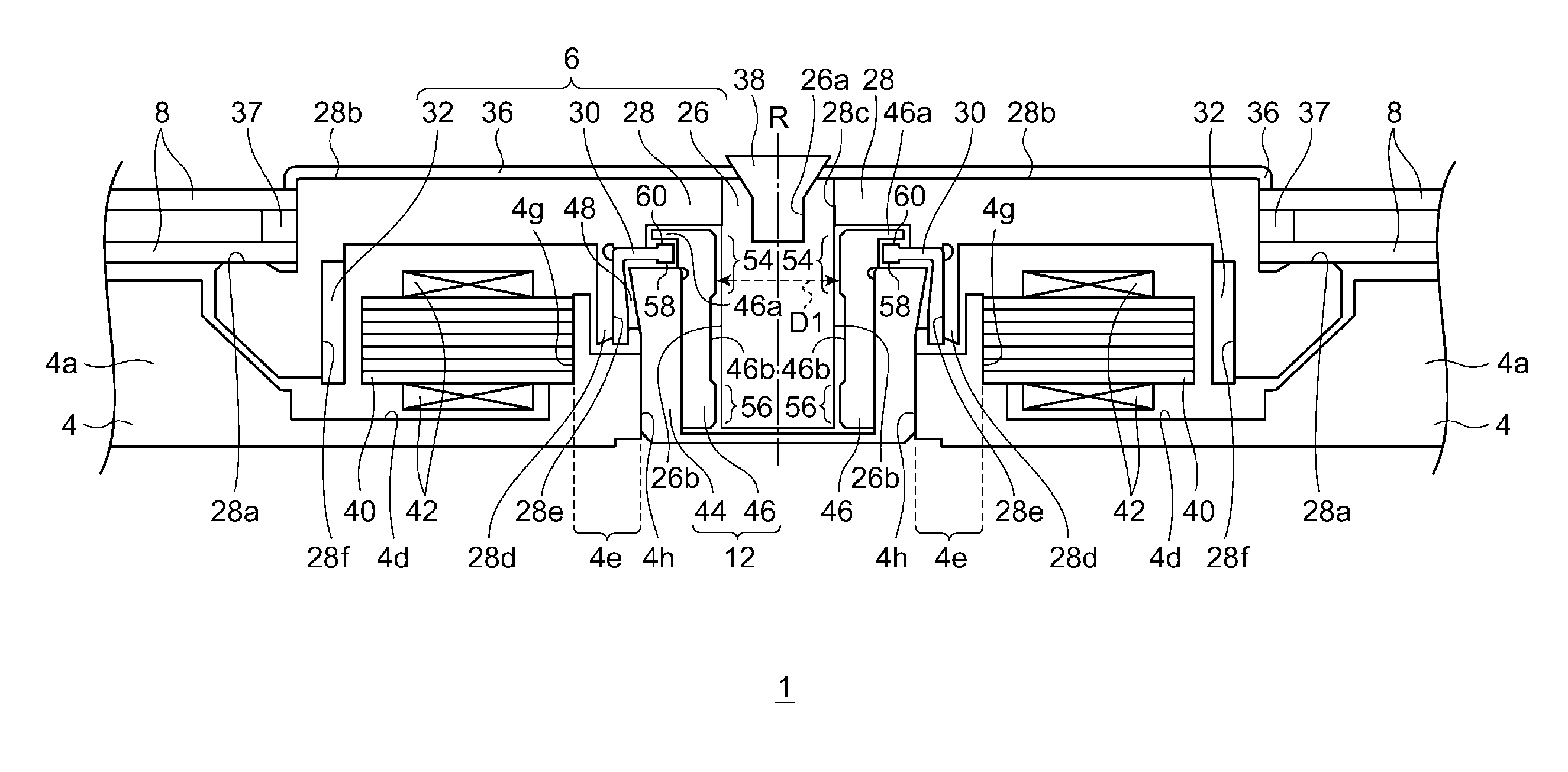
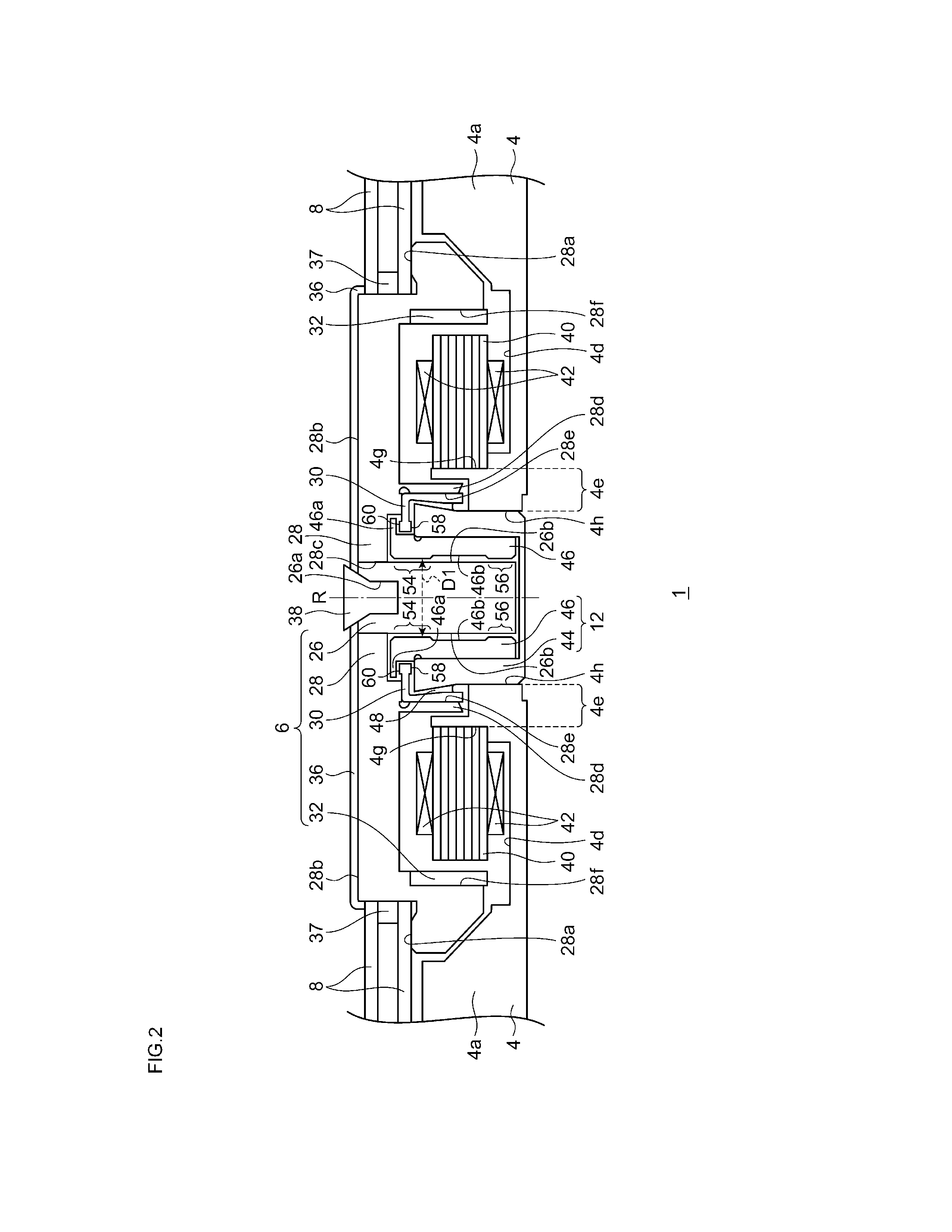
[0025]A rotating device according to an embodiment adopts a fluid dynamic bearing. The rotating device comprises a rotor and a stator rotatably supporting the rotor via a lubricant. A dynamic pressure groove, which creates a dynamic pressure in the lubricant in the rotating mode of the rotating device, is formed on a region so that the dynamic pressure groove tapers from the region's side to center. This may allow more efficient creation of dynamic pressure.

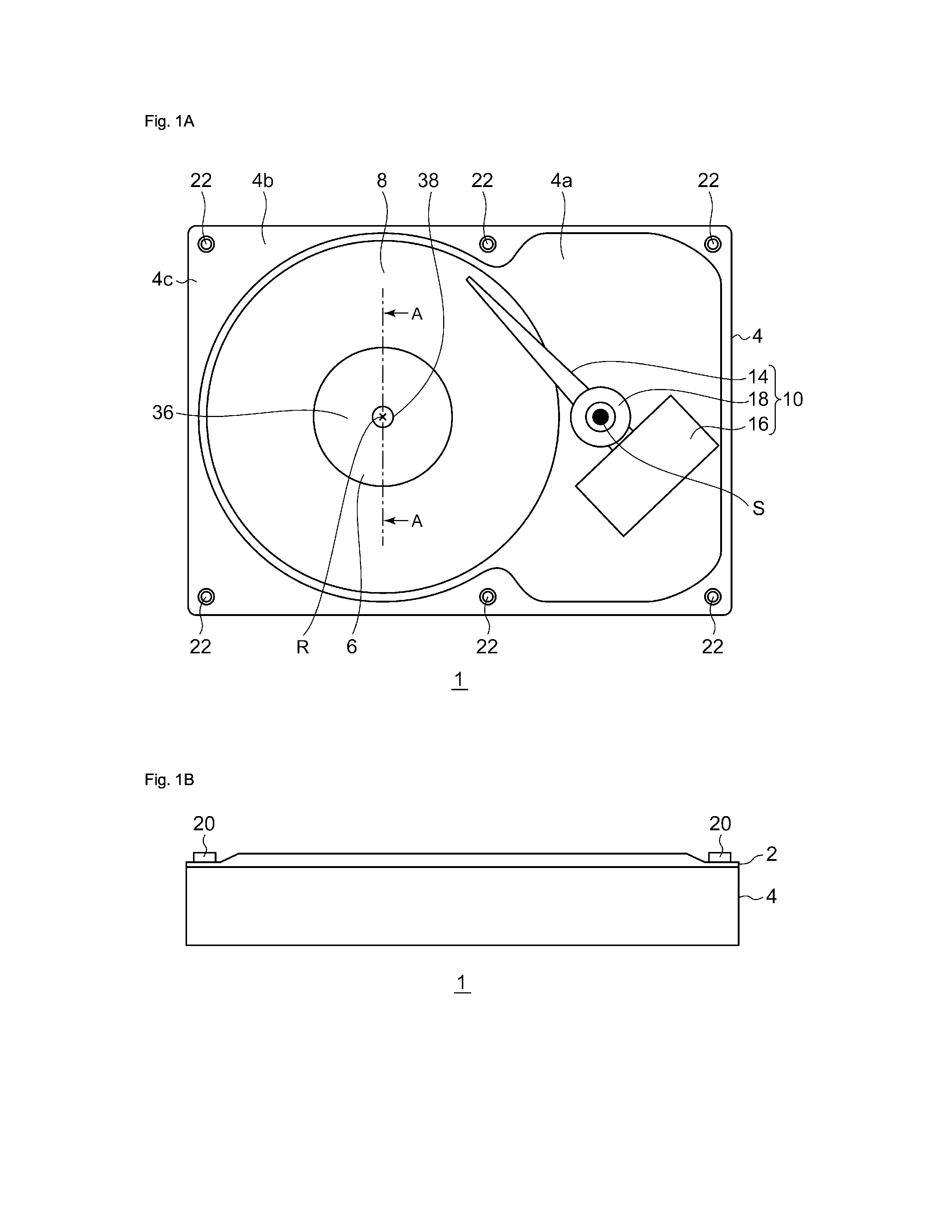
[0026]FIG. 1A and FIG. 1B are a top view and a side view, respectively, of the rotating device 1 according to this embodiment. FIG. 1A is the top view of the rotating devi...


PUM


Abstract

A rotating device comprises a stator configured to rotatably support a rotor via a lubricant. A first zonal region is formed on an inner surface of a sleeve. A plurality of grooves along a direction that crosses the first zonal region are formed on the first zonal region from each of both sides of the first zonal region. A groove formed from one side of the first zonal region is formed so that the closer a position in the groove is to the other side of the first zonal region, the shallower and the narrower the groove at the position will be. A groove formed from the other side is formed so that the closer a position in the groove is to the one side, the shallower and the narrower the groove at the position will be.

Description

CROSS-REFERENCE TO RELATED APPLICATIONS[0001]This application is based upon and claims the benefit of priority from the prior Japanese Patent Application No. 2012-006024, filed on Jan. 16, 2012, the entire content of which is incorporated herein by reference.BACKGROUND OF THE INVENTION[0002]1. Field of the Invention[0003]The present invention relates to a rotating device comprising a stator configured to rotatably support a rotor via a lubricant.[0004]2. Description of the Related Art[0005]Disk drive devices, such as hard disk drives, have become miniaturized. The capacity of a disk drive device has also been increased. Such disk drive devices have been installed in various types of electronic devices. In particular, such disk drive devices have been installed in portable electronic devices such as laptop computers or portable music players.[0006]A fluid dynamic bearing is a known bearing for the disk drive device. In a fluid dynamic bearing, a lubricant is injected into a gap betwe...

Claims


Application Information

Patent Timeline
IPC IPC(8): H02K7/08
CPCH02K5/1675H02K7/085F16C2240/30F16C17/026F16C33/107H02K7/086F16C2240/70F16C2240/40F16C2240/42
Inventor KODAMA, MITSUOSUZUKI, KEISUKEYAMADA, TAKUJIMORI, SHIGEYOSHI
Owner SAMSUNG ELECTRO MECHANICS JAPAN ADVANCED TECHNOLOGY CO LTD
Learn More