Radio Link Failure Recovery Control in Communication Network Having Relay Nodes

a communication network and relay technology, applied in the field of radio link failure recovery control in communication network having relay nodes, can solve problems such as direct application of quadruplexing options such as the ones shown in fig. 8/i>, disrupt channel estimation mechanisms implemented in lte based networks, communication systems such as lte based networks, etc., to facilitate the enhancement of lte-advanced networks and network performan

Inactive Publication Date: 2013-07-18
NOKIA SOLUTIONS & NETWORKS OY
View PDF3 Cites 56 Cited by
  • Summary
  • Abstract
  • Description
  • Claims
  • Application Information

AI Technical Summary

Benefits of technology

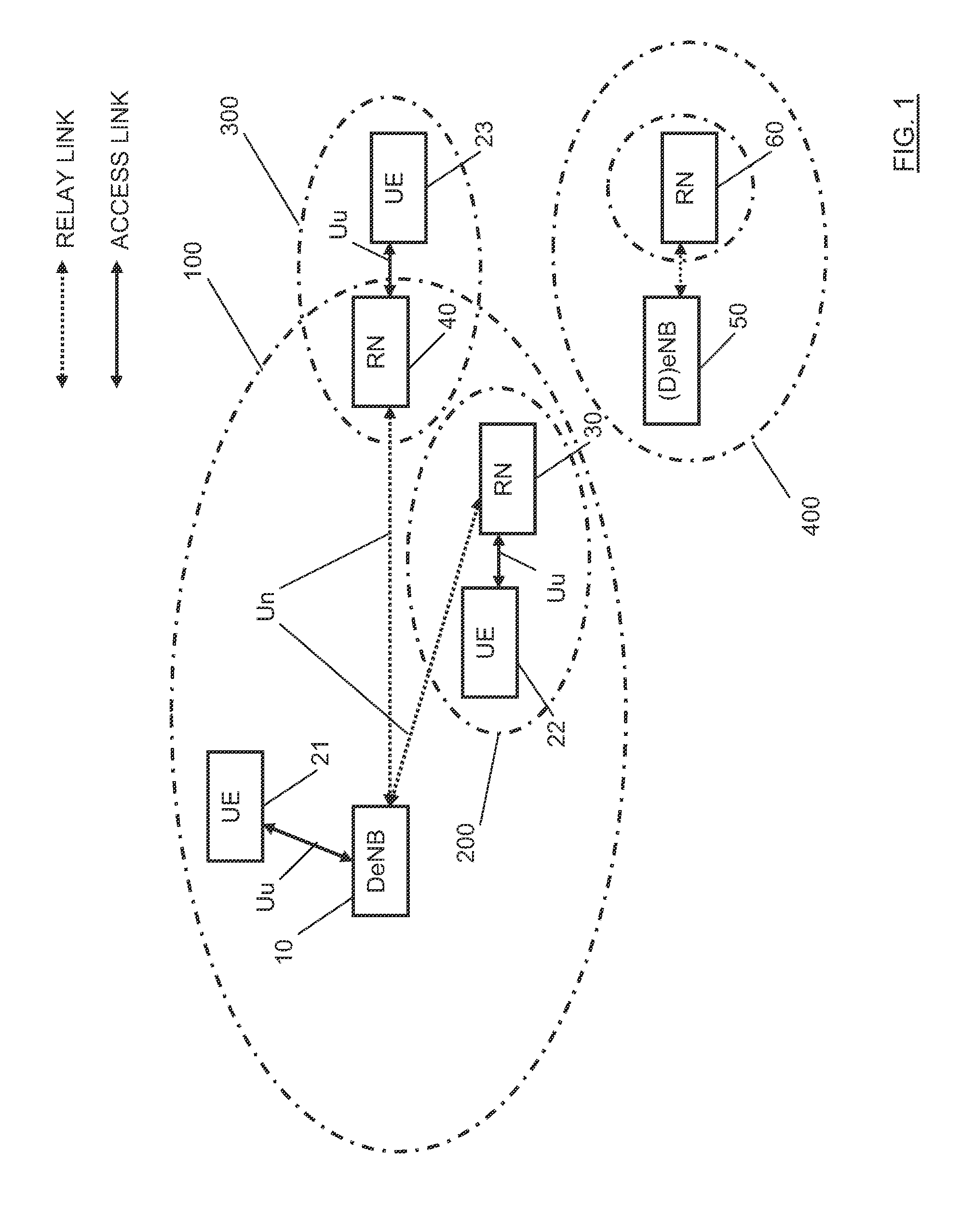
[0029]Thus, it is an object of the invention to provide an apparatus, method and computer program product by means of which an improved mechanism for controlling a radio link failure recovery procedure in a communication network having relay nodes is provided. Specifically, it is an object of the invention to provide an apparatus, method and computer program product by means of which an RLF recovery in a communication network using a relay concept, such as a relay enhanced LTE-advanced network, is facilitated when an RLF in a link between a UE and an RN and / or in a link between a RN and a network control node (such as a DeNB) occurs.
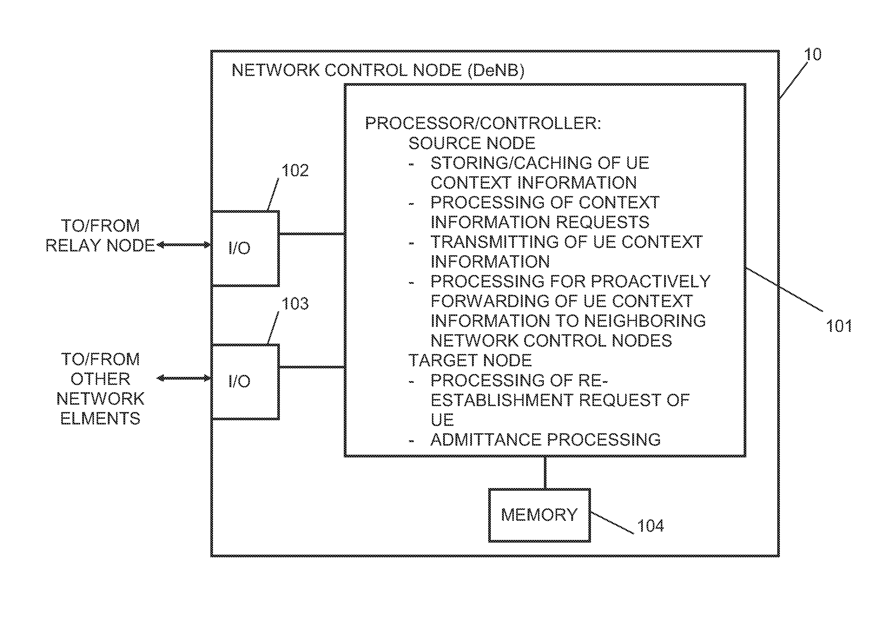
[0058]By proactively forwarding the context information of the RN (i.e. of UEs connected thereto) to candidate neighboring network elements, such as neighboring DeNBs, even before a radio link failure occurs (i.e. the possibility thereof is detected), the network control node controlling the respective RN (such as the DeNB) can further facilitate and accelerate a recovery procedure in case it becomes necessary. By means of a function that in case an RN detects a degrading of e.g. the Uu link of one of its UEs, it requests the controlling DeNB to forward the context information of that UE towards candidate neighbors for handing over the UE, a pre-handover action is implemented which supports a quick recovery in case the radio link deteriorates, for example, very fast so that a proper handover is not possible.
[0059]Furthermore, the proposed mechanism comprising a scheme of pre-forwarding UE context information enables that a handover is performed only when required, in particular in the context of RLF, and only at one cell, so that unnecessary resource reservations that might result in the rejection of the handover requests of other UEs are not required. Due to the caching of the context information at the network control node (DeNB), such context information can be retrieved also very fast.

Problems solved by technology

However, a direct application of the quadruplexing options such as the ones shown in FIGS. 8a and 8b on for example an LTE sub-frame basis may be problematic.
The reason is that it may disrupt channel estimation mechanisms implemented in LTE based networks which operate by sending scattered reference signals (RS).
A general problem to be dealt with in communication systems, in particular wireless communication systems such as LTE based networks, is a failure in the link between network elements.
Such link failures comprise, for example a so-called Radio Link Failure (RLF).
There are many situations which may cause RLF.
For example, in an LTE based system, apart from sudden and persistent bad radio link conditions, RLF may be due to several factors, such as a handover failure (handover procedure is started, but the radio link between the source eNB and the UE deteriorates so fast that the UE is not able to receive the RRC reconfiguration message needed to start accessing the target eNB; it can also be that for some reason it was not possible to access the target eNB and synchronize with it), or when the UE leaves the service area (this may happen if an active UE leaves the service area of the serving cell suddenly; the probability of this happening is high if the UE is not active, because it can be in DRX mode (with a long DRX cycle) and travelling fast, and when it wakes up it can find itself outside the serving area of the source eNB).

Method used


Image

  • Radio Link Failure Recovery Control in Communication Network Having Relay Nodes
  • Radio Link Failure Recovery Control in Communication Network Having Relay Nodes
  • Radio Link Failure Recovery Control in Communication Network Having Relay Nodes

Examples


Embodiment Construction

[0072]In the following, examples and embodiments of the present invention are described with reference to the drawings. For illustrating the present invention, the examples and embodiments will be described in connection with a communication system which may be based on a 3GPP LTE-advanced system where one or more relay nodes are used as extensions of the access network subsystems in the cells. However, it is to be noted that the present invention is not limited to an application in such a system or environment but is also applicable in other communication systems, connection types and the like.

[0073]A basic system architecture of a communication network may comprise a commonly known architecture comprising a wired or wireless access network subsystem and a core network. Such an architecture comprises one or more access network control units, radio access network elements, access service network gateways or base transceiver stations, with which a UE is capable to communicate via one...


PUM


Abstract

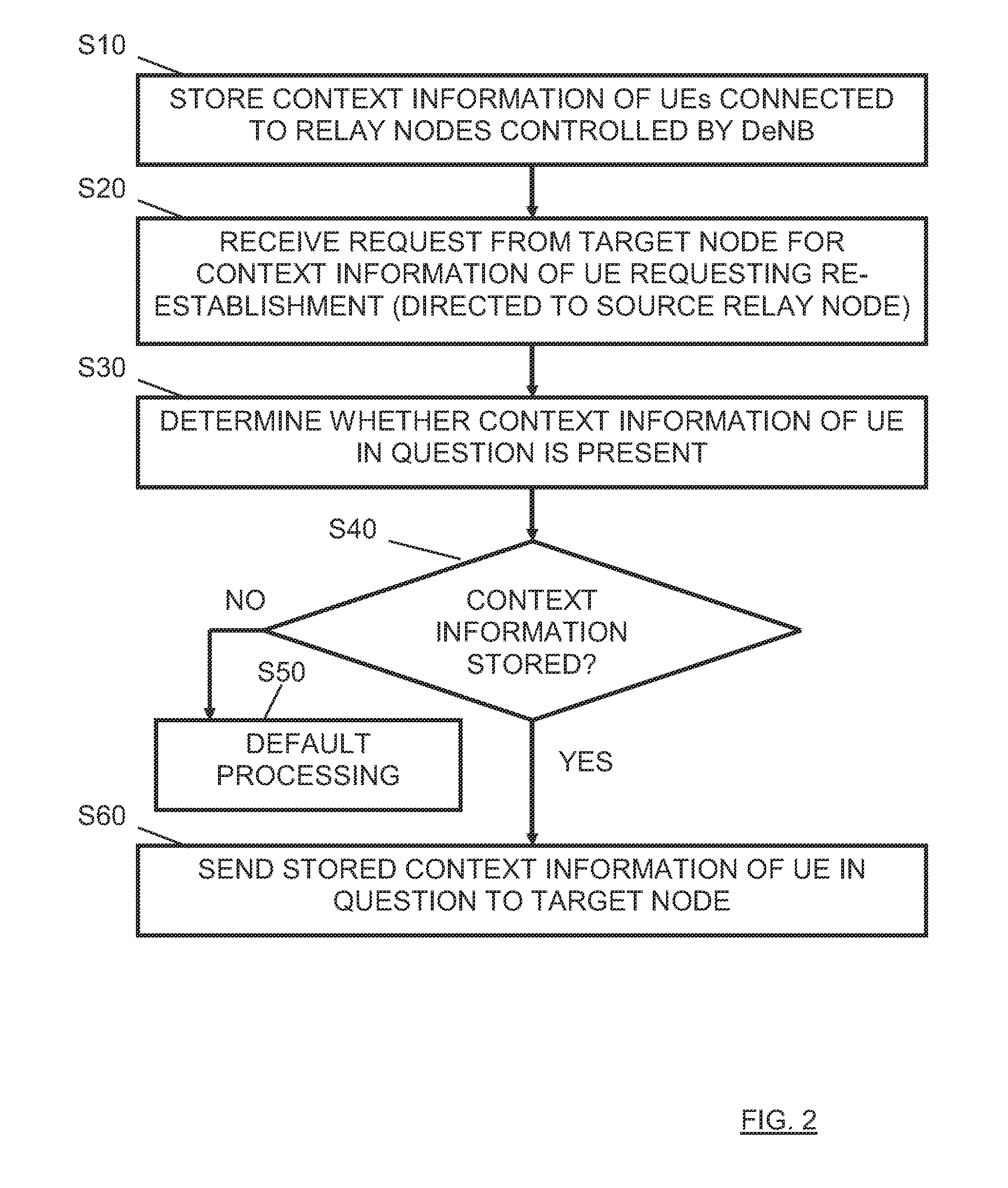
There is proposed a mechanism for controlling a radio link failure recovery procedure in a communication network having relay nodes, wherein a network control node, such as a DeNB, forwards cached UE context information to a target network node which is contacted by an UE for re-establishment after radio link failure and requests, since it does not have the context information, the context information for the UE in question. Context information can also be proactively forwarded from the network control node to candidate neighboring network nodes when it is detected that a radio link failure between a relay node and the network control node, or between the relay node and a UE is possible.

Description

BACKGROUND OF THE INVENTION[0001]1. Field of the Invention[0002]The present invention relates to a method, apparatus and computer program product providing a mechanism for controlling a radio link failure recovery procedure in a communication network having relay nodes. In particular, the present invention is related to a mechanism providing functions for improving a recovery performance in a communication network when a radio link failure occurs in a link to a relay node as an extension of an access service subsystem.[0003]2. Related Background Art[0004]Prior art which is related to this technical field can e.g. be found by the technical specifications TR 36.806 (current version: 9.0.0), TS 36.300 (current version: 9.3.0), TR 36.814 (current version: 9.0.0), TS 36.423 (current version: 9.2.0) of the 3GPP.[0005]The following meanings for the abbreviations used in this specification apply:3GPP—3rd generation partnership projectDeNB—donor eNBDL—downlinkDRX—discontinuous receptioneNB—e...

Claims


Application Information

Patent Timeline
Patent Type & Authority Applications(United States)
IPC IPC(8): H04W24/04H04W36/00H04W76/02
CPCH04B7/2606H04W36/0033H04W36/30H04W24/04H04W84/047H04W88/12H04W76/028H04W76/19H04W36/305
Inventor RAAF, BERNHARDREDANA, SIMONETEYEB, OUMER
Owner NOKIA SOLUTIONS & NETWORKS OY
Why Eureka
Try Eureka