Cooling systems for submersible pumps

Active Publication Date: 2013-07-18
ZENIT INT SPA
View PDF33 Cites 20 Cited by
  • Summary
  • Abstract
  • Description
  • Claims
  • Application Information

AI Technical Summary

Benefits of technology

[0038]The main advantages of the separation between the cooling circuit and the mechanical seal volume are the following:
[0039]The mechanical seal works in oil and may lead to an increased life endurance of the mechanical seal. This may improve the reliability of the submersible pump.
[0040]The oil in the mechanical seal chamber may allow the seal system to increase its efficiency, so the total efficiency of the pump may rise.
[0041]The separation of the cooling circuit from the mechanical seal area

Problems solved by technology

The closed jacket cooling system does not require external water, which can be expensive and sometimes not easily available in the sump, but at the same time, since it uses the dirty liquid for cooling, has major drawbacks.
As mentioned before the disadvantage is the use of the same pumped liquid.
In pumps intended mainly for sewage, or any other dirty water, the use of the pumped water for cooling can create problems and requires frequent maintenance and cleaning of the cooling circuit.
One disadvantage of this prior art system is that, in cooling installed system version, the pumps comes in contact with water not only in the cooling system, but also in the mechanical seals chamber.
This last characteristic is the main disadvantage of this prior art system.
At the same time when this incident happens, it means that the sewage water has entered the first mechanical s

Method used


Image

  • Cooling systems for submersible pumps
  • Cooling systems for submersible pumps
  • Cooling systems for submersible pumps

Examples


Example

[0052]In accordance with the present invention, a cooling system is proposed that preferably uses a closed loop for the cooling liquid. A preferred cooling liquid may be glycol, or a similar cooling liquid. The present invention provides for two separate chambers for the mechanical seals and the closed cooling circuit.

[0053]In this solution the mechanical seals can be always immersed in oil and a leakage detector can be installed like in a conventional pump.

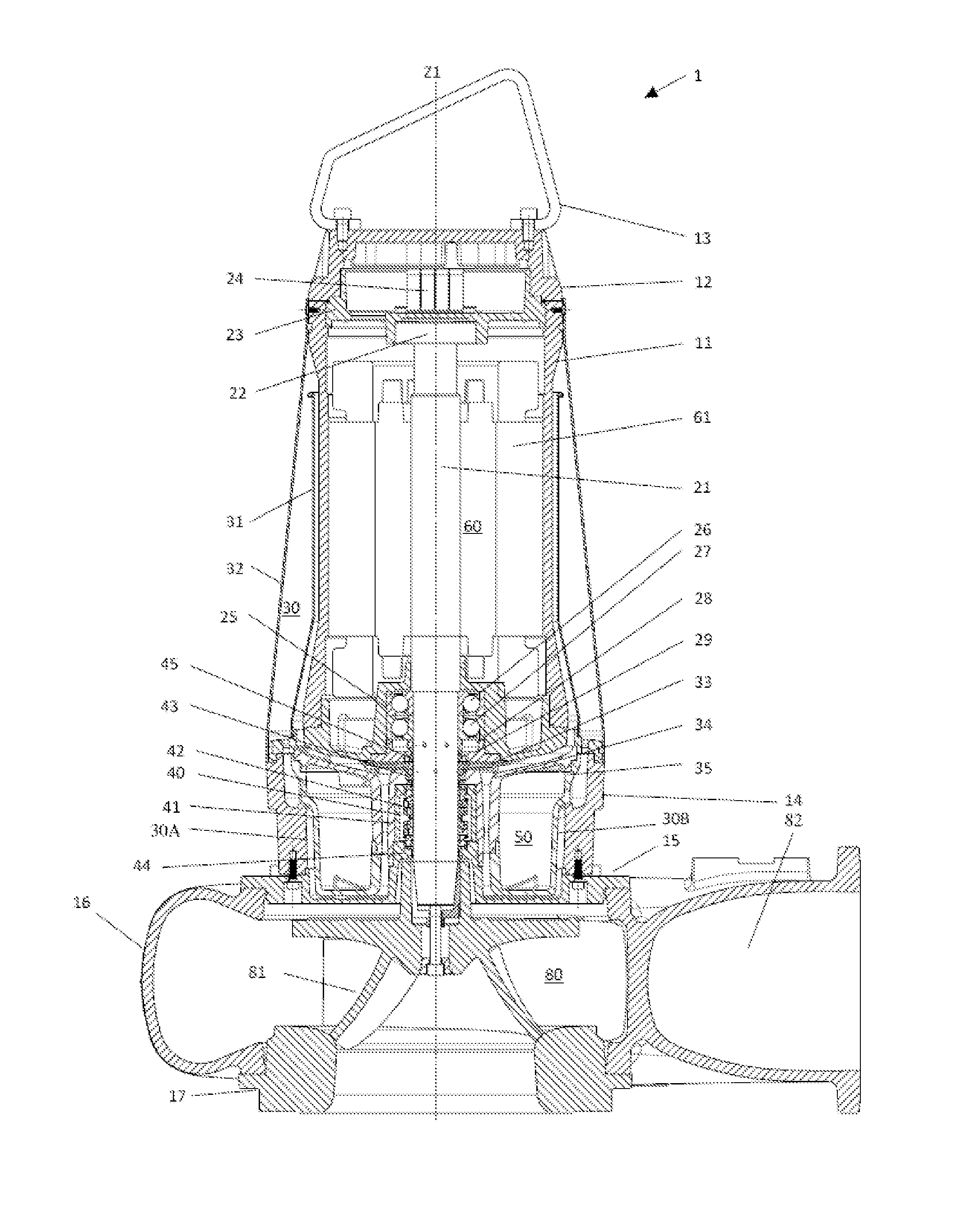
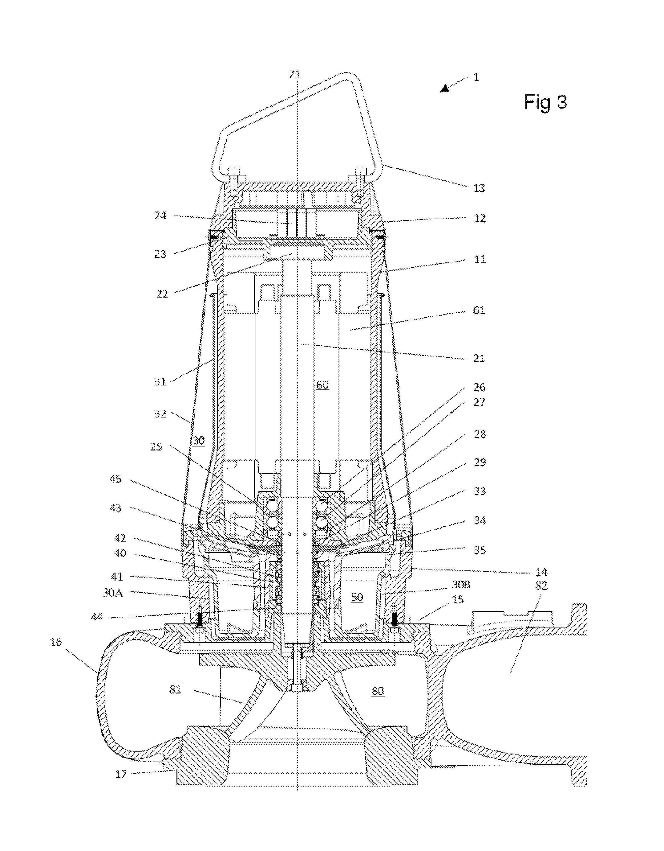
[0054]With reference to FIG. 3, a pump, preferably a submersible pump 1 is shown arranged for emptying drain wells, basements, tanks, or similar.

[0055]The pump 1 comprises a motor case 11 having substantially the shape of a hollow cylinder and extending along a first longitudinal axis Z1. At the upper end, the motor case 11 is closed by a motor lid 12. A handle 13 is associated with the motor lid 12 and is arranged for being held by a user in order to raise and / or transport the pump 1. The motor lid 12 also encloses a terminal bl...


PUM


Abstract

A pump (1) is disclosed, the pump (1) comprising a shaft (21) for driving an impeller (81) in a pump chamber (80); an electrical motor chamber (60) extending essentially circumferentially around a motor section of the shaft (21); a cooling circuit chamber (30) for being filled with a cooling liquid; and a mechanical seal chamber (40) extending essentially circumferentially around a seal section of the shaft (21), with the mechanical seal chamber (40) adapted for being filled with oil. The pump (1) may be a submersible pump.

Description

FIELD OF THE INVENTION[0001]The present invention relates to cooling systems for submersible pumps. More particularly, it relates to closed circuit cooling systems for submersible pumps.TECHNICAL BACKGROUND OF THE INVENTION[0002]Today, in general only two different cooling systems are used for submersible pumps: closed jacket cooling system and open jacket cooling system.[0003]The first system, closed jacket cooling, uses the same pumped liquid to cool the motor thanks to a cooling jacket installed around the cast iron casing, as schematically shown in FIG. 1. In this case the liquid must not contain big solid parts to prevent the cooling circuit flow to be reduced or clogged. The mechanical seals are arranged in an oil chamber. The closed jacket cooling system does not require external water, which can be expensive and sometimes not easily available in the sump, but at the same time, since it uses the dirty liquid for cooling, has major drawbacks. As mentioned before the disadvanta...

Claims


Application Information

Patent Timeline
IPC IPC(8): F04D13/08F04D29/12F04D29/58F04D29/06
CPCF04D13/08F04D29/061F04D29/126F04D29/58F04D13/086F04D29/06F04D29/12F04D29/588F04D15/0263F04D29/5806F04D25/0686
Inventor BOTTAN, DAVIDE
Owner ZENIT INT SPA
Why Eureka
Try Eureka