Bone Resection Jig Used in Artificial Knee Joint Replacement Surgery

a knee joint replacement and bone resection technology, applied in the field of bone resection jigs, can solve the problems of long surgical time, troublesome operation, complex constitution, etc., and achieve the effect of not requiring a great deal of skill to operate, light weight and simple operation

Active Publication Date: 2013-07-18
NAKASHIMA MEDICAL +1
View PDF7 Cites 45 Cited by
  • Summary
  • Abstract
  • Description
  • Claims
  • Application Information

AI Technical Summary

Benefits of technology

[0009]According to the bone resection jig of the present invention of claim 1, the primary constituent parts are extremely few in number, which are a spacer block to be inserted into the resection region of the femur and tibia, a reference pin guide that appropriately sets the flexion position, and an aiming member that sets the resection range for the back of the distal end of the femur; and the constitution of the various constitutional elements of these parts is also simple. Accordingly, the bone resection jig of the present invention has a small number of constituent parts, is light in weight and inexpensive, and is simple in operation, thus not requiring a great deal of skill to operate.
[0010]According to the means of claim 2, the hollow box does not block the field of view when the spacer block is inserted. According to the means of claim 3, the angle between the tip and back of the distal end of the femur can be matched to the shape of the femur side part of the artificial knee joint, and thus the femur side part can be inserted accurately and securely. According to the means of claim 4, the reference pin guide can be set accurately in the right attitude, which is horizontal. According to the means of claim 5, the back of the distal end of the femur can be set to resection planes of a variety of levels and angles. According to the means of claim 6, the femur can be placed in flexion of 90° with the reference spacer part of the spacer block left inserted after a prescribed amount of the distal end of the femur and the proximal end of the tibia are resected.

Problems solved by technology

However, the invention of this prior art checks (measures) the tension of ligaments in both extension and flexion positions; accordingly, the operation is troublesome, and it requires a longer surgical time.
Further, the constitution is complex, and it includes many moving parts and adjustment parts, and further it requires numerous operation steps that are difficult and require proficiency.
In addition, it is heavy and expensive.

Method used


Image

  • Bone Resection Jig Used in Artificial Knee Joint Replacement Surgery
  • Bone Resection Jig Used in Artificial Knee Joint Replacement Surgery
  • Bone Resection Jig Used in Artificial Knee Joint Replacement Surgery

Examples


Embodiment Construction

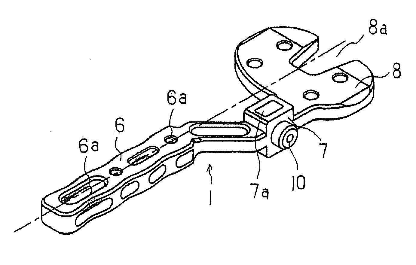
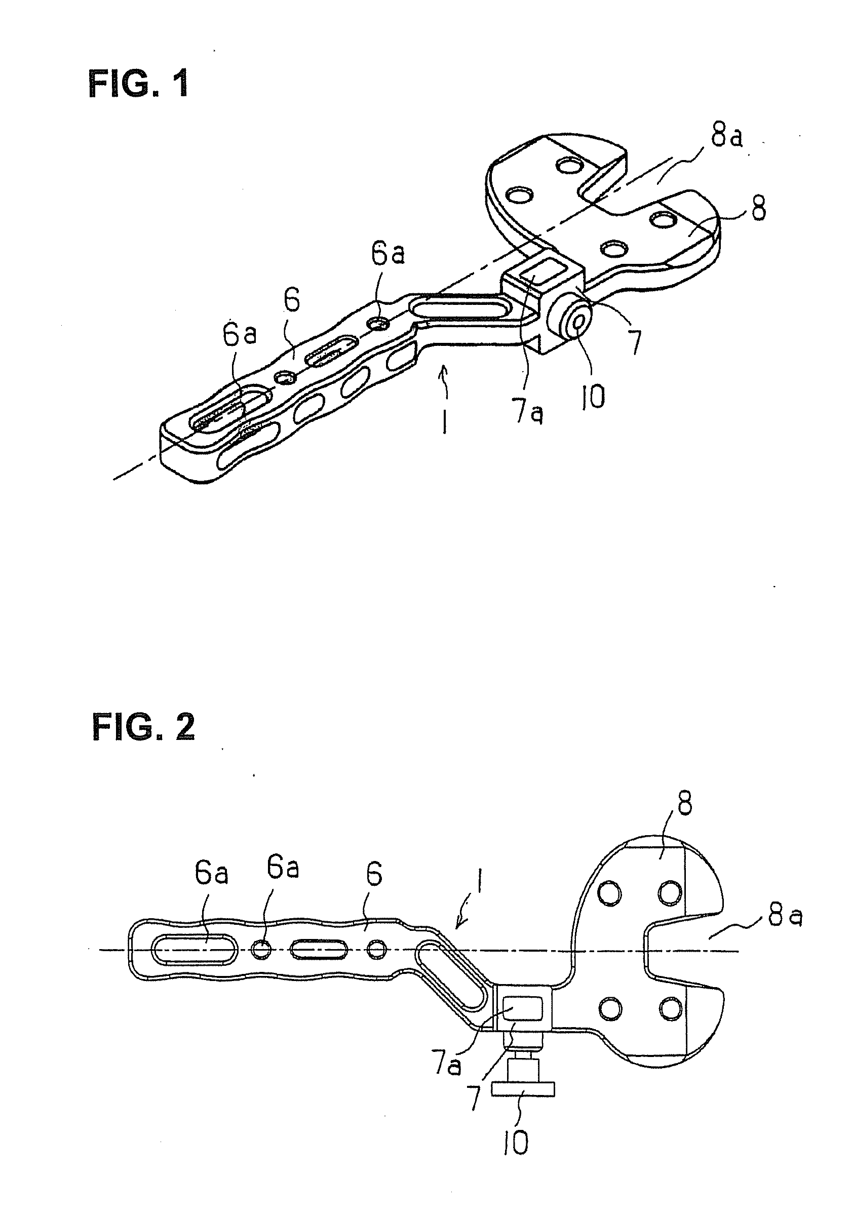
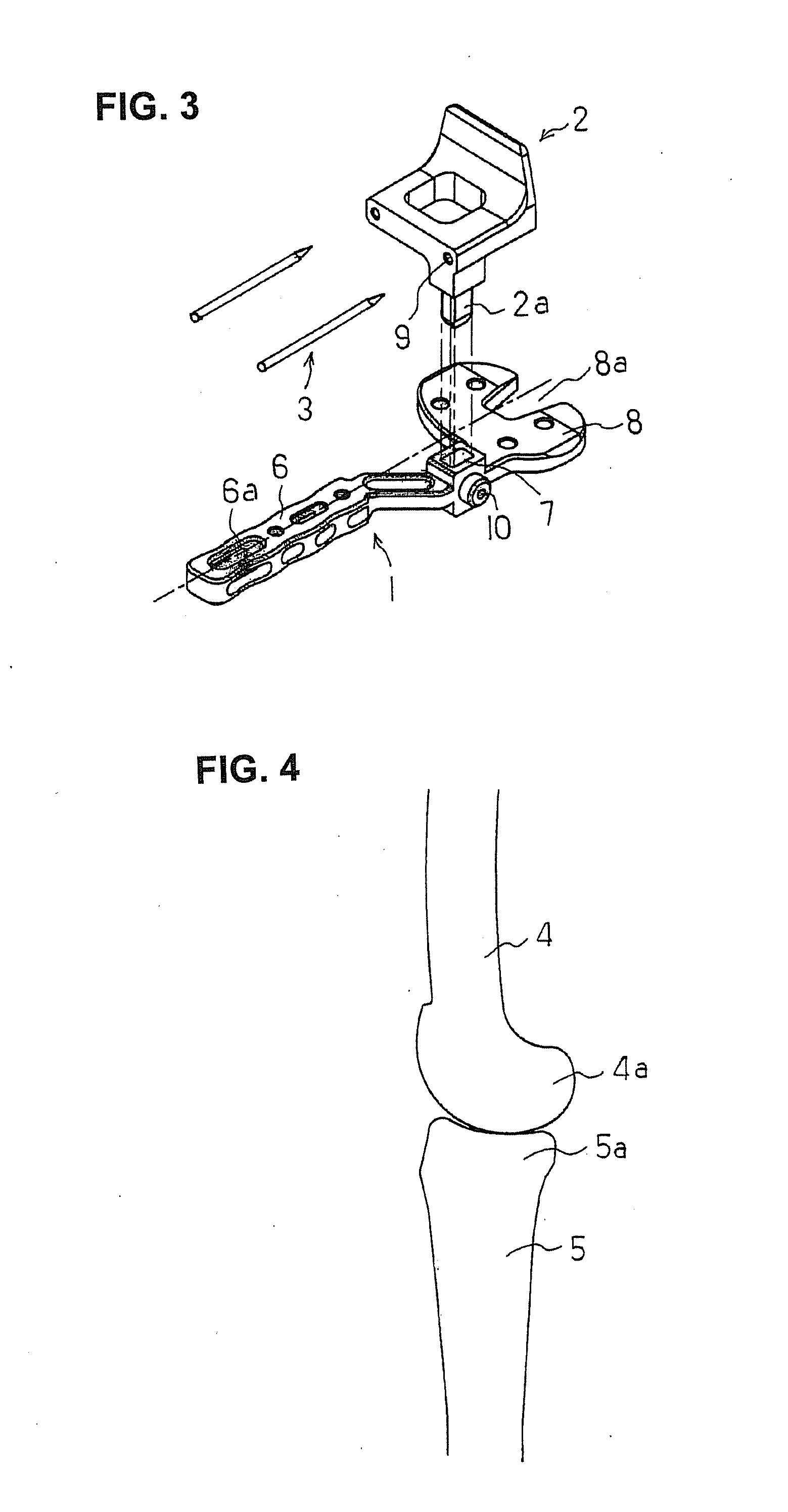
[0026]Modes for carrying out the present invention will be described below with reference to the drawings. FIG. 1 is a perspective view of a spacer block 1 that comprises a main body of the bone resection jig (hereafter, called “the jig”) used during artificial knee joint replacement surgery in accordance with the present invention, FIG. 2 is a top view, and FIG. 3 is a perspective view of the spacer block 1, a reference pin guide 2, and reference pins 3. In the following, reference is made to front / back, up / down, and left / right directions. These are in reference to the knee in standing position and seen from the front and lateral sides. “Front” refers to the front of the knee (the patella side), and “upper” refers to the femur side; and for “left / right” the left side is a lateral side in the case of the left knee.

[0027]The spacer block 1 is one that is inserted into a resection region of a resected distal end of a femur 4 and a resected proximal end of a tibia 5, and it supports th...


PUM


Abstract

A bone resection jig that can make ligament tension equal at extension and flexion positions without any actual measurements when resecting femur and tibia during artificial knee joint replacement surgery. The bone resection jig used in artificial knee joint replacement surgery includes a spacer block (1) comprised of a grip (6), a hollow box (7) that is provided on an other end side of the grip and has a vertical hole (7a) therein, and a reference spacer part (8) that extends out from the hollow box (7) and is adapted be inserted into the resection region between femur and tibia; a reference pin guide (2) which, when the femur and tibia are in the flexion position, is inserted into the vertical hole (7a) of the hollow box, extends on the reference spacer part (8) to the other end side of the grip so as to come into contact with a resection plane (FH) of the tip of the distal end of the femur, and is formed with guide holes (9) for guiding reference pins (3) to be installed from a front side into the resection plane (FH) of the tip of the distal end of the femur; and an aiming member (12) which is, after the spacer block (1) has been removed from a space between the femur and tibia leaving the reference pins (3), brought onto the reference pins (3) by being guided thereby, the aiming member being provided with an indicator (14) that indicates a resection plane (FR) at a back of the distal end of the femur when the aiming member (12) comes into contact with the resection plane (FH) of the tip of the distal end of the femur.

Description

TECHNICAL FIELD[0001]The present invention relates to a bone resection jig used during artificial knee joint replacement surgery.BACKGROUND ART[0002]When a knee joint suffers knee osteoarthritis, rheumatoid arthritis, or bone tumors, or suffers external injury or the like, the part subject to joint damage at the tips of the femur and tibia is resected, and those parts are replaced with an artificial joint. This artificial knee joint, as conventionally seen, comprises a combination of a femur component, which has two condyles of medial and lateral, and a tibia component, which has a joint plate that bears these two condyles and allows them to rotate; and it is desirous that artificial knee joints that are comprised of such condyles and joint plates preferably be movable similarly to a biogenic knee joint.[0003]The femur and tibia are connected by numerous ligaments, and extension and flexion of them are made by tensioning and relaxing these ligaments. It is particularly desirable tha...

Claims


Application Information

Patent Timeline
Patent Type & Authority Applications(United States)
IPC IPC(8): A61B17/17
CPCA61B17/025A61B17/155A61F2/4684A61B2017/0268A61F2/389A61B17/1764
Inventor KANEYAMA, RYUTAKUKURAMOTO, KOICHIYAMAMOTO, KEITAROUMARUYAMA, DAISUKE
Owner NAKASHIMA MEDICAL
Why Eureka
Try Eureka