Lightning protection fastener and mounting method thereof

a technology of protection fasteners and fasteners, which is applied in the direction of threaded fasteners, screwed fasteners, aircraft static dischargers, etc., can solve the problems undesirable cases, and achieve the effects of reliably confined arcs, preventing the pressure of sealant in the cap from becoming excessively high, and preventing the cap from floating up

Active Publication Date: 2013-07-25
MITSUBISHI AIRCRAFT
View PDF3 Cites 38 Cited by
  • Summary
  • Abstract
  • Description
  • Claims
  • Application Information

AI Technical Summary

Benefits of technology

[0012]The sealant 4 such as described above has high viscosity. Therefore, if a gap between the end face 3a of the cap 3 on the opening side and the member 5 such as a wing panel is reduced in final stages of mounting the cap 3, it becomes difficult for the sealant 4 to spill out through the gap, increasing the pressure of the sealant 4 held between the cap 3 and the member 5 such as a wing panel.
[0016]The present invention has been accomplished in view of these technical problems and has an object to provide a lightning protection fastener and a method for mounting the lightning protection fastener which can prevent a cap from floating up and reliably confine arcs.
[0025]According to the present invention, when the cap is mounted, the cap is pressed against the fastener member shaft and the fastening member, and the sealant filled into the cap is caused to spill out of both the opening and through-hole, making it possible to prevent the pressure of the sealant in the cap from becoming excessively high, prevent the cap from floating up, and thereby reliably confine arcs.

Problems solved by technology

This case is also undesirable because it may become impossible to confine arcs reliably between the cap 3 and the member 5 such as a wing panel.

Method used


Image

  • Lightning protection fastener and mounting method thereof
  • Lightning protection fastener and mounting method thereof
  • Lightning protection fastener and mounting method thereof

Examples


first embodiment

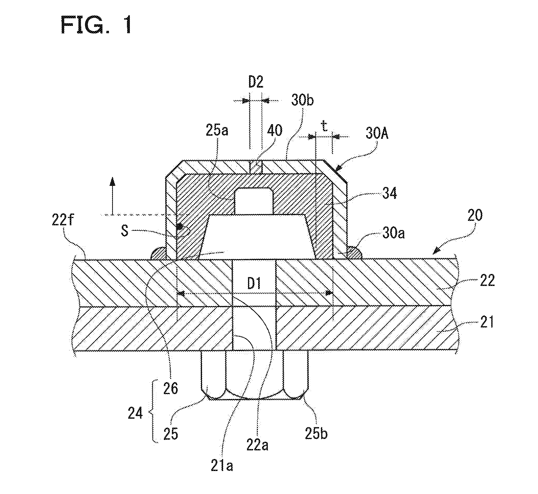
[0034]FIG. 1 is a sectional view of part of a wing constituting an airframe of an aircraft to which a lightning protection fastener according to an embodiment of the present invention is applied.

[0035]As shown in FIG. 1, an outer shell of a wing 20 is formed from an wing panel (first member) 21 made, for example, of CFRP (Carbon Fiber Reinforced Plastics), which is a composite material of carbon fiber and resin, or a metal material such as aluminum alloy. Being provided in the wing 20, structural members for reinforcement, fuel tanks, and various instruments are fixed to the wing panel 21 via members (second member) 22 such as stays made of a metal material such as aluminum alloy. The members 22 such as stays are mounted on the wing panel 21 by fasteners 24.

[0036]The fastener 24 includes a pin-shaped fastener member 25 and a collar (fastening member) 26 attached to the fastener member 25 on an inner side of the wing 20.

[0037]Generally, the fastener member 25 and collar 26 are made o...

second embodiment

[0068]A second embodiment of the lightning protection fastener and the cap for the lightning protection fastener according to the present invention will be shown next. Components different from the first embodiment will mainly be described below: common components with the first embodiment described above are denoted by the same reference numerals in drawings as the corresponding components in the first embodiment, and description thereof will be omitted.

[0069]As shown in FIG. 3A, compared to the cap 30A according to the first embodiment, a cap 30B according to the present embodiment has a tubular body 50 provided on an outer periphery of the through-hole 40.

[0070]In mounting the cap 30B on the fastener member 25, the tubular body 50 allows the sealant 34 overflowing through the through-hole 40 to be accommodated in the tubular body 50. This enables to keep the fingers of workers who mount the cap 30B free from the sealant 34, improving operating efficiency.

[0071]Also, if a front-en...

third embodiment

[0074]A third embodiment of the lightning protection fastener and the cap for the lightning protection fastener according to the present invention will be shown next. Components different from the first embodiment will mainly be described below: common components with the first embodiment described above are denoted by the same reference numerals in drawings as the corresponding components in the first embodiment, and description thereof will be omitted.

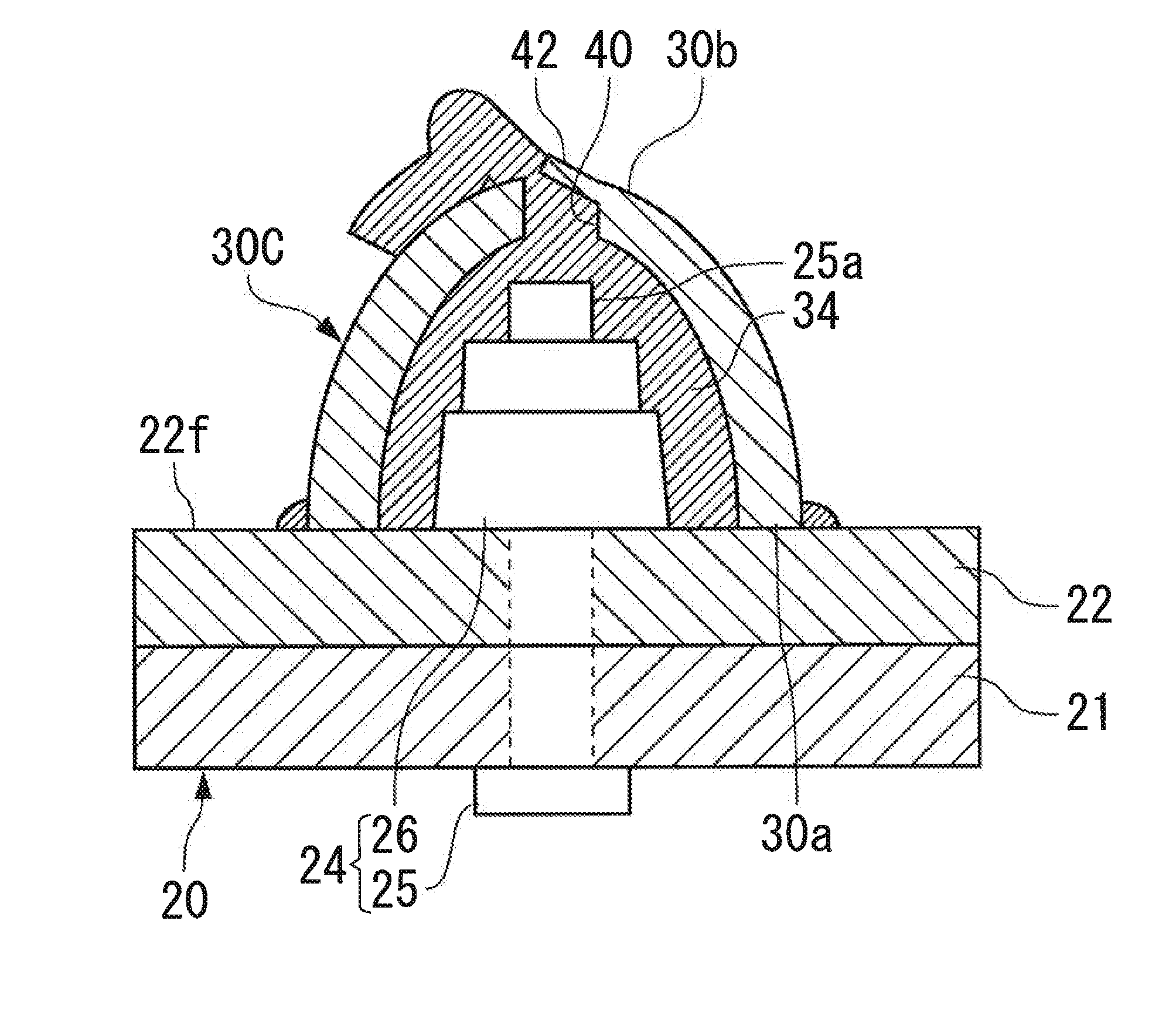
[0075]As shown in FIGS. 5A and 5B, a cap 30C according to the present embodiment has a lid 42 provided on the through-hole 40, where the lid 42 is smaller in thickness than the cap 30C around the through-hole 40. The lid 42 has an outside diameter smaller than the hole diameter of the through-hole 40, and part of the lid 42 in the circumferential direction is integrally coupled to the cap 30C.

[0076]As shown in FIG. 5C, when the cap 30C is mounted on the fastener member 25, the lid 42 described above changes a flow direction of the se...


PUM


Abstract

A sealant 34 filled into a cap 30A is caused to overflow through both an opening in a first end portion 30a of the cap 30A and a through-hole 40 of the cap 30A when the cap 30A is pressed against a fastener member 25. With regard to the cap 30A, a ratio between inside diameter D1 of the opening on the side of the first end portion 30a and hole diameter D2 of the through-hole 40 in the second end portion 30b is set as follows: 0.10≦D2 / D1 ≦0.27.

Description

BACKGROUND OF THE INVENTION[0001]1. Field of the Invention[0002]The present invention relates to a lightning protection fastener used for an airframe of an aircraft, and especially for wings, as well as to a method for mounting the lightning protection fastener.[0003]2. Description of the Related Art[0004]Each wing of an airframe of an aircraft generally has a hollow structure and a wing panel forming a wing surface is fixed to a structural member in the wing by using fastener members (fasteners).[0005]In so doing, the wing panel and structural member are fastened together by passing a pin-shaped fastener member, from outside the wing, through through-holes formed in both the wing panel and the structural member in the wing and fixing a front-end portion of the fastener member with a fastening member (collar) from inside the wing.[0006]Besides, in the wings and a fuselage, structural members other than the wing panels as well as fixing members for equipment are fixed and fastened by...

Claims


Application Information

Patent Timeline
Patent Type & Authority Applications(United States)
IPC IPC(8): F16B39/22
CPCF16B39/225B64D45/02F16B37/14F16B33/004F16B5/02
Inventor ASAHARA, YUJIYAMAKOSHI, HIDEOIYOMASA, ATSUHIRONISHIMURA, WATARUTARUMI, TAKEYASUWATANABE, YASUNORIHASHIGAMI, TORURIKUKAWA, HIROSHIIMAMURA, HIDEOTANIGUCHI, NAOKI
Owner MITSUBISHI AIRCRAFT
Why Eureka
Try Eureka