Air Humidification System

Active Publication Date: 2013-07-25
AIR DISTRIBUTION TECH IP LLC
View PDF2 Cites 30 Cited by
  • Summary
  • Abstract
  • Description
  • Claims
  • Application Information

AI Technical Summary

Benefits of technology

[0016]Embodiments of the invention thus provide a residential or commercial humidifier for use in a central HVAC duct to increase the humidity level of the air passing across a wetted evaporator pad. The humidifier may have either an integral fan or a flow-through or by-pass housing for

Problems solved by technology

The drained water is wasteful and costly.
Moreover, the waste of water by the typical “constant” water-flow humidifier is generally not constant.
Anything that acts to reduce the output capacity of the humidifier can likewise increase the waste of water in a constant flow system.
Reductions in the surface area and/or size of the evaporator pad, degradation of the physical condition of the evaporator pad, reductions in the flow rate of air through the evaporator pad, and reductions in the temperature of the air flowing through the evaporator pad can all reduce the capacity of the humidifier and therefore increase the amount of wasted water.
Systems provided with higher than typical water pressure may not operate at a maximum output potential due to excessive water flowing through the evaporator pad, i.e., flooding of the pad.
This condition can reduce the effectiveness of the humidifier and waste even more water.
Some HVAC systems include filtration systems which become dirty, resulting in reduced air flow.
This would result in diminished airflow and evaporation and increase the amount of water wasted.
This uncertainty makes humidifier drain waste and output ratings (typically a single number of gallons per day) somewhat unreliable, especially for predicting the amo

Method used


Image

  • Air Humidification System
  • Air Humidification System
  • Air Humidification System

Examples


Embodiment Construction

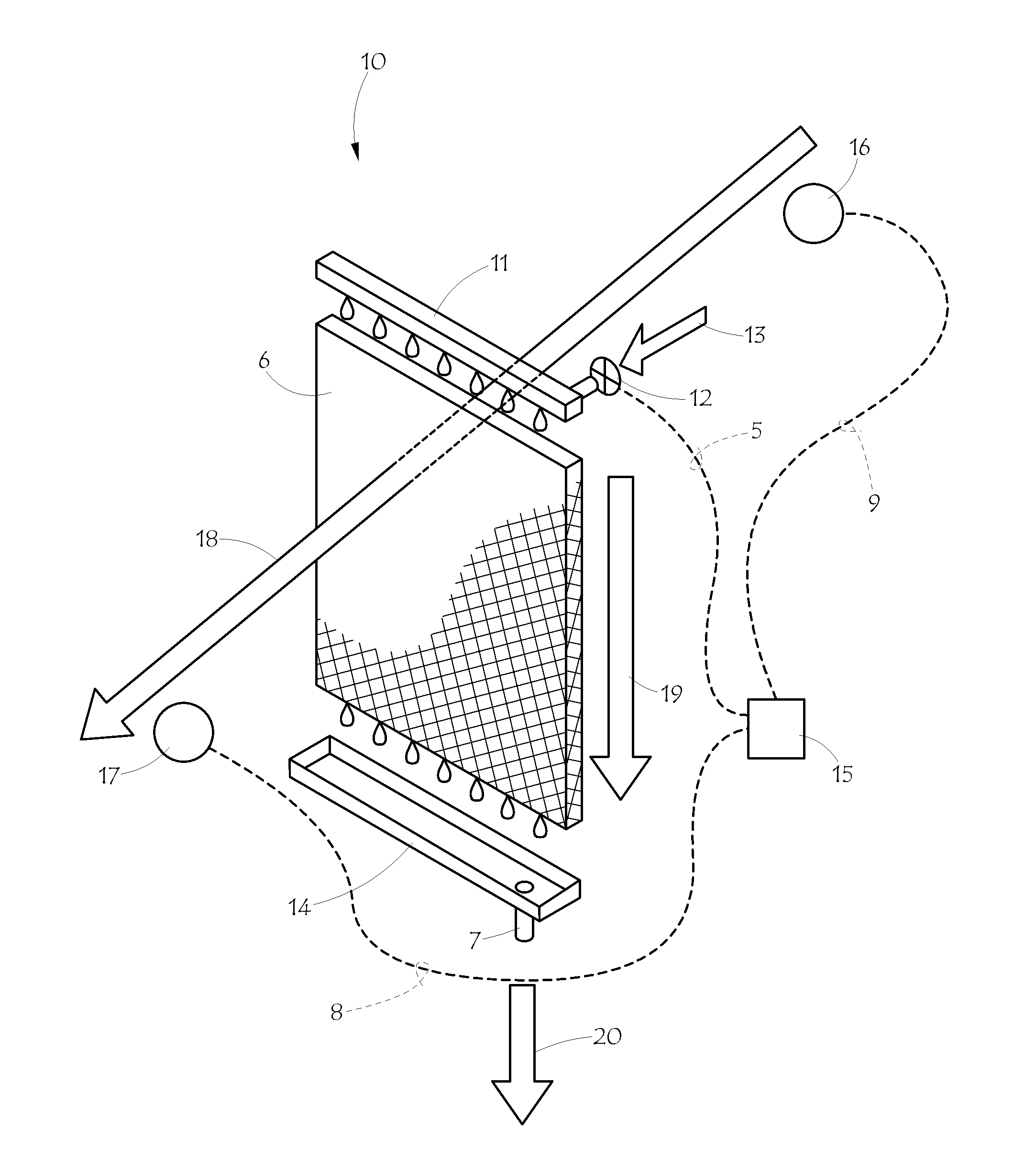
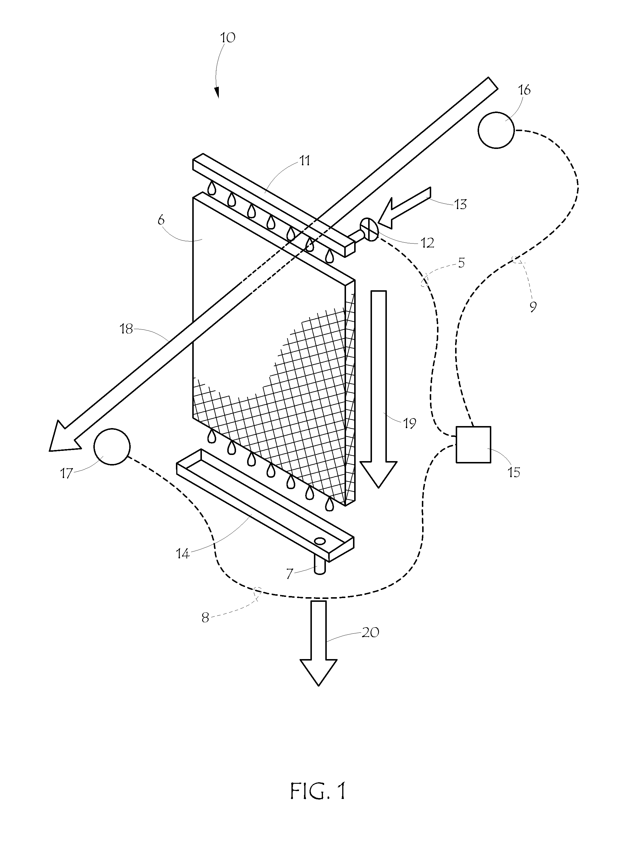
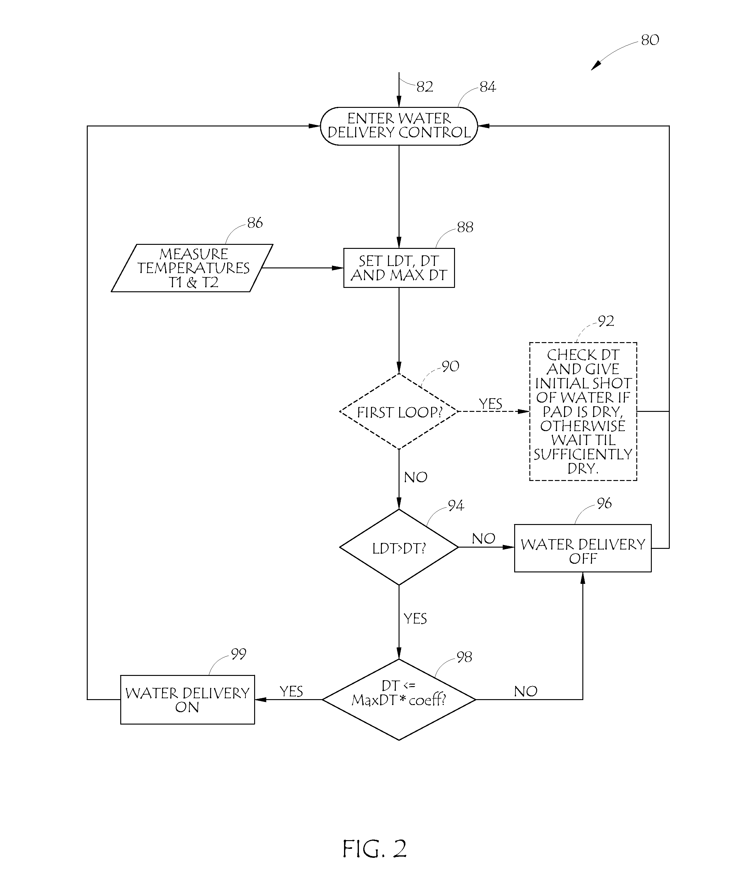
[0029]The invention consists of an air humidification system employing a housing to contain all of the parts, an evaporator pad, a water delivery system to deliver water to the evaporator pad, a drain system to allow excess water to flow away from the humidification system, temperature sensors to measure the air temperature being supplied to the humidification system and the temperature of the air flowing out of the humidification system, and a control system to operate the electrical portions of the system. The control system controls water flow to the pad to maintain the temperature differential of the air upstream and downstream of the pad near its maximum value. At the same time the control system uses a small amount of water, maintaining a small amount of drain water flow in proportion to the output. Other optional features may be included, some of which will be described herein.

[0030]FIG. 1 is a schematic representation of an embodiment of the invention showing the key parts a...


PUM

PropertyMeasurementUnit
Temperatureaaaaaaaaaa
Fractionaaaaaaaaaa
Humidityaaaaaaaaaa

Abstract

A humidifier for use in a central HVAC duct. The humidifier includes a water delivery system for applying water to an evaporator pad, a drain system for removing excess water that is not evaporated, and a control system employing two temperature sensors directly measuring the temperature of the air before and after the evaporator pad. The control system uses the two temperatures to adjust the water flow across the pad by cycling the water delivery system so that drain water is minimized while maximizing the evaporative capacity of the humidifier thus satisfying the humidification load as quickly as possible with the least amount of drain water. The humidifier may have either an integral fan or a flow-through housing for passing air across the wetted evaporator pad to increase the humidity level of the air.

Description

BACKGROUND OF THE INVENTION[0001]1. Field of the Invention[0002]This invention relates generally to air humidifiers such as used in a central HVAC system, more particularly to a water-saving humidifier control, and specifically to an air humidifier control system based on temperature differential which maintains minimal drain water with maximal humidification output regardless of environmental conditions.[0003]2. Description of the Prior Art[0004]Humidifiers have become integral components in residential and commercial heating, ventilating and air-conditioning (“HVAC”) systems. Typical central HVAC systems comprise a duct system in combination with a blower or fan and controls for selective or constant circulation of air through the duct system. Heating components are utilized to provide an influx of heat upon demand or as a function of the overall HVAC system. The energy present in the air, added by the heating system, is used to evaporate water from the humidifier. Typically, the ...

Claims


Application Information

Patent Timeline
IPC IPC(8): F24F11/00F24F6/04
CPCF24F11/0008F24F6/043F24F6/04B01F23/215
Inventor SCHNEIDER, STEPHEN M.KARL, MITCHELL A.GRAVES, RONALD W.
Owner AIR DISTRIBUTION TECH IP LLC
Why Eureka
Try Eureka