Mobile electronic device positioning unit

Inactive Publication Date: 2013-07-25
OCTA
View PDF14 Cites 56 Cited by
  • Summary
  • Abstract
  • Description
  • Claims
  • Application Information

AI Technical Summary

Benefits of technology

[0007]It is one aspect of embodiments of the present invention to provide a multi-functional gripping device that provides an ergonomic and efficient way to hold an electronic device that also functions

Problems solved by technology

One drawback of these devices is that in some instances their size and shape renders them difficult to position and use in a hands-free manner.
After holding the electronic device for an extended time the user will often become tired and the amount of holding force and associated stability applied to the electronic device will dec

Method used


Image

  • Mobile electronic device positioning unit
  • Mobile electronic device positioning unit
  • Mobile electronic device positioning unit

Examples


Embodiment Construction

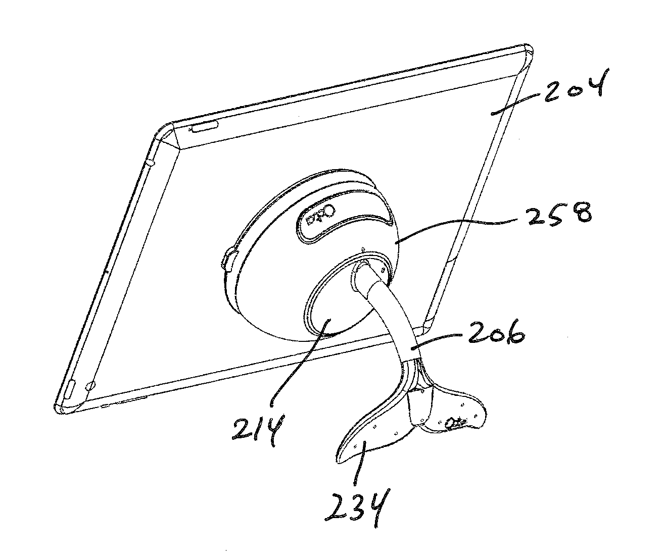
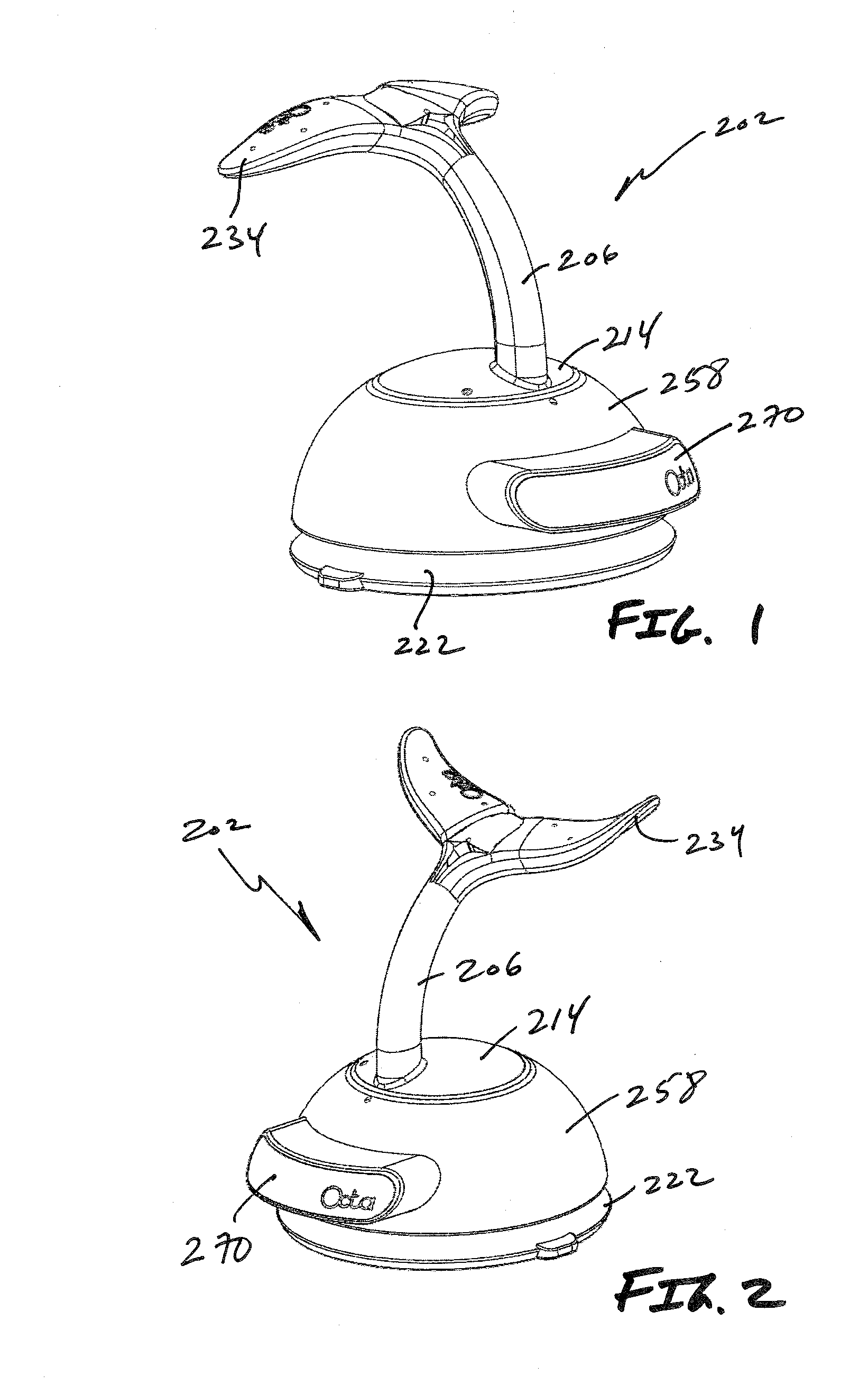
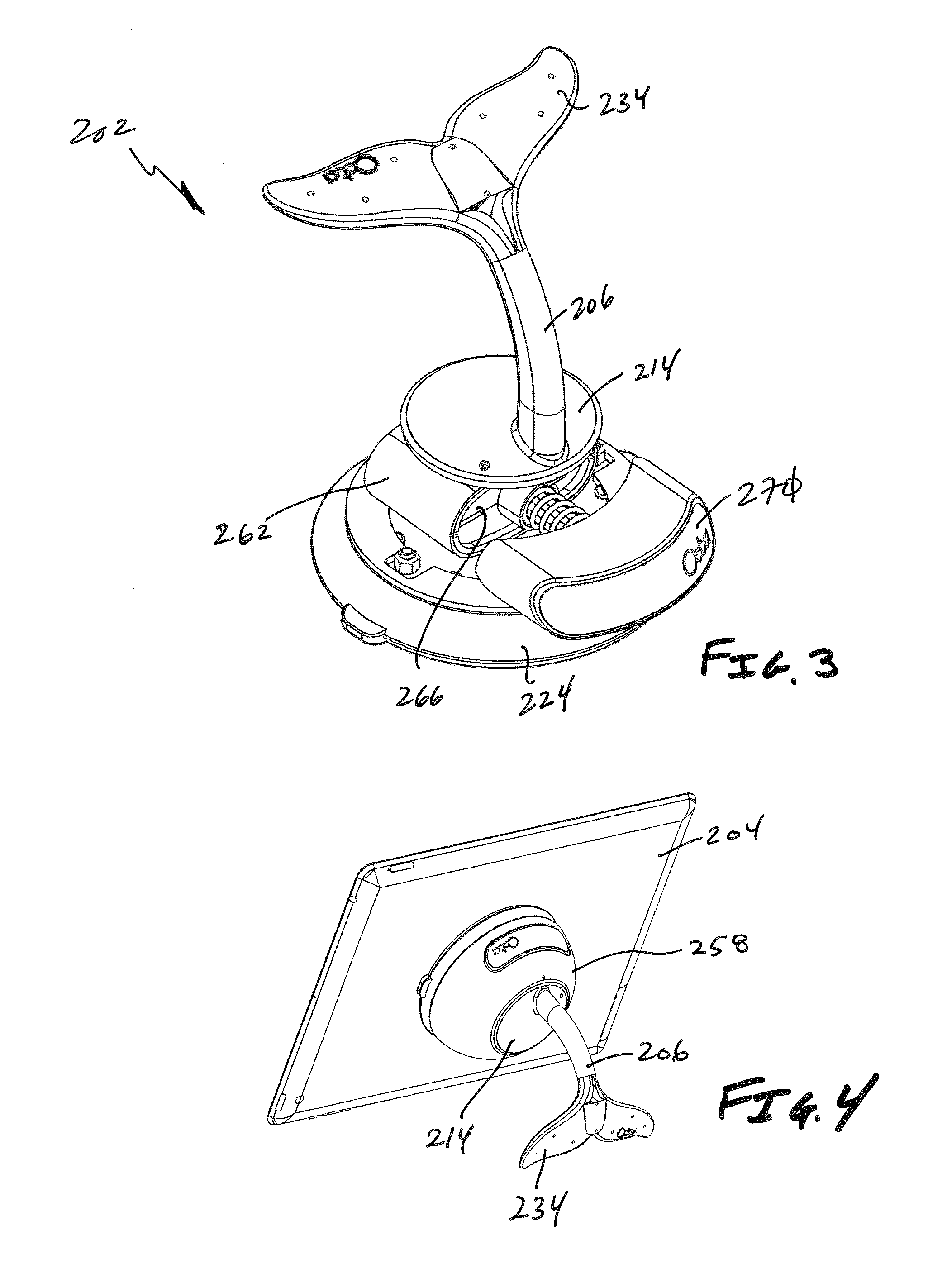
[0055]Referring now to FIGS. 1-6, one embodiment of the present invention is shown wherein the positioning grip 202 is selectively interconnectable to a dock 258 that further interconnects to the electronic device 204. The dock 258 accommodates the suction mechanism 222 or other interconnection device. The suction cup 224 of the suction mechanism 222 may be actuated in any fashion known, including those described above. In one embodiment, however, the suction cup 224 is pneumatically associated with at least one cylinder 262 having a finger-actuated piston 266. The suction cup 224 may be made of an elastomeric material. It may also contain or be reinforced with a stiffener made from a material having a higher Young's modulus (stiffness) to aid in retaining the suction cup in a configuration that provides a superior holding force compared to a simple unrestrained elastomeric suction cup. The piston 266 may be associated with a single button 270 or a plurality of buttons wherein movem...


PUM


Abstract

A positioning grip or device is provided that is selectively interconnectable to a portable electronic device. The positioning grip is preferably interconnected to the portable electronic device via a mechanism that provides a suction cup and allows for selective rotation of the portable electronic device. The positioning grip also includes a support having at least one selectively deflectable arm.

Description

[0001]This application is a Continuation-In-Part of PCT application No. PCT / US2011 / 045921, filed with the WIPO on Jul. 29, 2011, which designates the United States, and which claims the benefit of U.S. Provisional Patent Application Ser. No. 61 / 424,973, filed Dec. 20, 2010, and U.S. Provisional Patent Application Ser. No. 61 / 503,240, filed Jun. 30, 2011, U.S. Provisional Patent Application Ser. No. 61 / 249,973, filed Dec. 20, 2010, and U.S. Provisional Patent Application Ser. No. 61 / 414,747, filed Nov. 17, 2010, the entire disclosures of which are incorporated by reference herein.[0002]This application also claims the benefit of U.S. Provisional Patent Application Ser. No. 61 / 693,397, filed Aug. 27, 2012, the entire disclosure of which is incorporated by reference herein.[0003]This application also claims the benefit of U.S. Provisional Patent Application Ser. No. 61 / 709,321, filed Oct. 3, 2012, the entire disclosure of which is incorporated by reference herein.FIELD OF THE INVENTION...

Claims


Application Information

Patent Timeline
IPC IPC(8): F16M13/02
CPCF16M11/10F16M13/00F16M13/02F16M13/04F16M13/022
Inventor TROTSKY, KEVIN
Owner OCTA
Why Eureka
Try Eureka